
With the rapid advancement of smart cockpits and Advanced Driver Assistance Systems (ADAS), the automotive “nervous system” is undergoing a profound evolution: shifting from traditional power transmission (low-speed) to high-frequency data transmission. Amidst this digital transformation, Rosenberger innovatively introduced the HSD (High-Speed Data) connector in 2007. Engineered specifically for harsh automotive environments, HSD has established itself as a foundational industry standard for in-vehicle infotainment, camera systems, and high-speed Ethernet, delivering exceptional signal integrity and immunity to interference. This guide will provide an in-depth analysis of the mechanical coding, material science, and high-frequency performance of HSD connectors.
What is HSD connector? (The Basics)
Four Core Mechanical Components
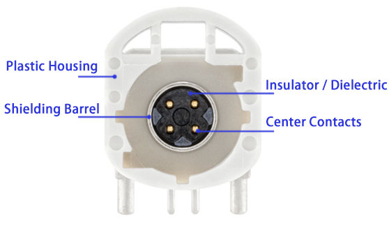
To ensure robust electrical performance and structural survival within harsh automotive environments, the HSD connector consists of four parts:
- Center Pin: Four copper alloy contacts transmitting differential signals.
- Insulator / Dielectric: High-performance plastic spacing contacts to maintain precise geometry and characteristic impedance.
- Outer Shield / Shielding Barrel: A die-cast zinc or copper sleeve ensuring continuous 360° EMC protection and containment.
- Plastic Housing: The external shell providing mechanical retention, audible latching, and key coding.
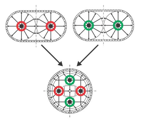
Star Quad layout: The Secret to High-Speed Data
Unlike standard parallel or twisted-pair wiring arrangements, HSD utilizes a specialized Star Quad layout. In this configuration, four insulated conductors are arranged symmetrically around a common central axis, forming a cross-section where the two diagonal pairs function as separate differential circuits. This spatial arrangement ensures that external electromagnetic fields affect all four conductors identically. Because the receivers measure the differential voltage between the diagonal pairs, the common-mode noise cancels out precisely. The Star Quad geometry significantly reduces crosstalk between adjacent lines and maintains a uniform 100Ω characteristic impedance, all within a compact cross-sectional area.
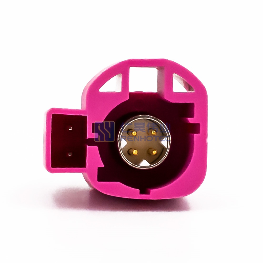
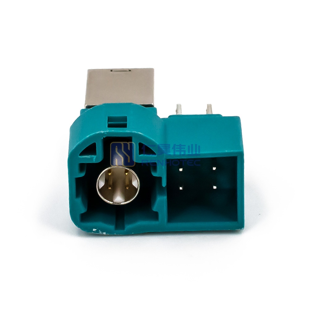
Regarding terminology, a clear structural distinction must be made: the HSD Pin represents the male header connector (typically mounted on the PCB side, featuring exposed pin contacts within the shroud), whereas the HSD Jack refers to the female connector assembly (typically integrated into the cable harness, housing the recessed spring sockets).
Core Attributes of HSD Systems
An automotive-grade HSD component must satisfy rigorous qualification standards before it can be integrated into a vehicle’s production bill of materials. These attributes are broadly categorized into six core performance dimensions:
| Performance Category | Key Metrics & Parameters | Technical Significance & Standards |
|---|---|---|
| Mechanical Performance | Mating Cycles: ≥ 25 engagement cycles Retention Force: ≥ 110 N |
Ensures mechanical endurance during service life and prevents accidental disconnection due to external pulling forces. |
| Material Performance | Housing: PBT-GF / PA66-GF Contacts: Copper Alloy (Gold/Silver Plated) |
Provides dimensional stability, high temperature resistance, and highly reliable contact interfaces. |
| Electrical Performance | Impedance: 100 Ω ± 15 Ω Insertion Loss: ≤ 0.1 dB up to 1 GHz Return Loss: ≥ 20 dB up to 1 GHz |
Preserves signal integrity across the high-frequency spectrum, minimizing reflections and signal attenuation. |
| Environmental Performance | Temperature: -40°C to +125°C Vibration: USCAR-2 / DIN IEC 60068 |
Guarantees reliable operation under extreme thermal cycling and severe chassis vibration profiles without signal micro-interruptions. |
| Electromagnetic Compatibility (EMC) | Screening Attenuation: ≥ 65 dB (up to 1 GHz) Transfer Impedance: ≤ 75 mΩ/m |
Provides effective mitigation against electromagnetic interference (EMI) in dense electronic routing environments. |
| Environmental Compliance | RoHS, REACH IMDS Data Entry: 100% Traceability |
Mandatory regulatory compliance for global automotive supply chains, logging every material substance down to its elemental composition. |
Key coding and Common HSD Connector Types
Mechanical Key Coding System
To prevent mis-mating during high-velocity assembly on automotive production lines, the HSD system employs a standardized mechanical key coding system (HSD Key Coding). The plastic housings feature unique internal and external rib patterns matched with specific industry colors. Mating is physically restricted to corresponding mechanical profiles. Code Z is universally designated as a neutral coding, allowing it to mate with all other mechanical configurations, which is highly useful for testing and diagnostic equipment.
Standardized HSD connector mechanical coding profiles and color matrix. (Actual coding assignments vary depending on OEM platform requirements and vehicle architecture.)
| Code | Color |
|---|---|
| A | Jet black |
| B | Cream |
| C | Signal blue |
| D | Claret violet |
| E | Leaf green |
| F | Nut brown |
| G | Blue grey |
| Code | Color |
|---|---|
| H | Heather violet |
| J | Beige |
| K | Curry |
| L | Yellow green |
| M | Pastel orange |
| O | Pastel green |
| Z | Water blue (Neutral) |
Single-Port vs. Multi-Port Variants
The standard 4-pin HSD connector serves as the foundational architecture, natively supporting power delivery concurrently over the high-frequency differential pairs using Power over Coax (PoC) or Power over Data Lines (PoDL) technology. To address complex integration requirements where supplemental discrete signals or isolated low-voltage power feeds are required alongside primary high-bandwidth data channels, the HSD family expanded into enhanced hybrid variants:
- HSD+2, HSD+4, HSD+8: These configurations incorporate additional external MQS (Micro Quadlok System) signal pins on the periphery of the main shielded Star Quad shell. These auxiliary pins enable simultaneous transmission of dedicated DC power lines or low-speed secondary control signals without invading the high-frequency shielded envelope.
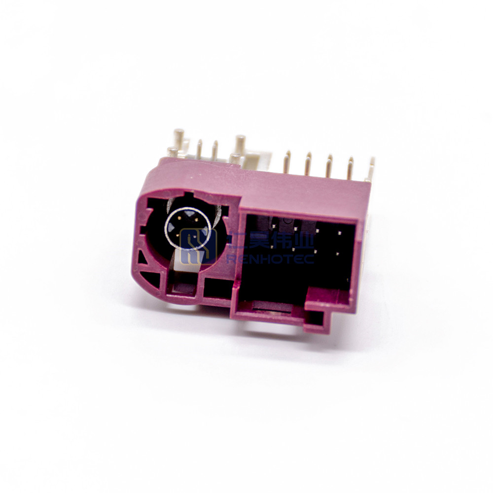
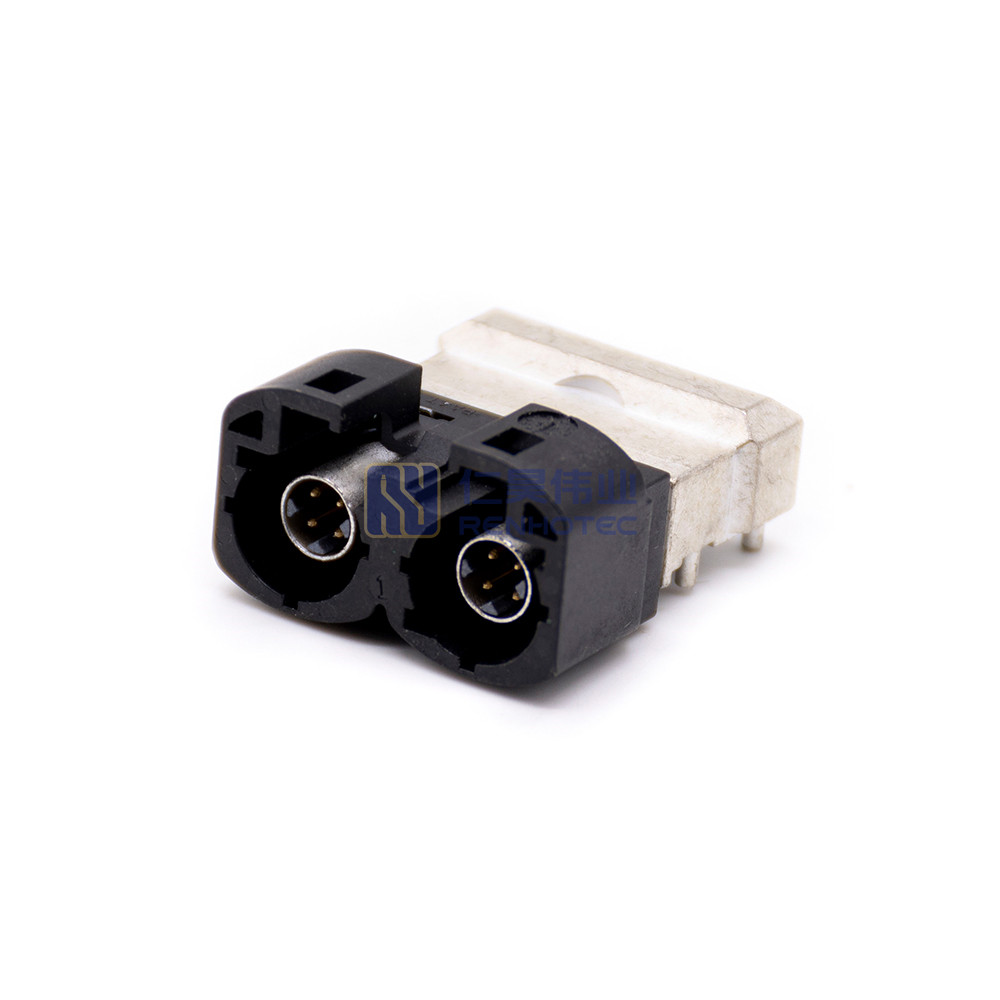
- Dual and Quad HSD Structures: Often called “Twin” or “Multi-port” blocks, these variants combine two or four separate HSD interfaces into a singular, unified multi-port plastic housing. They are widely utilized in dense domain routers, central gateways, and high-performance automated driving compute platforms where space on the PCB face is highly constrained, significantly reducing assembly time and component footprint.
How to Choose HSD Connector for Automotive Apps
FAKRA vs. HSD: When Should You Upgrade?
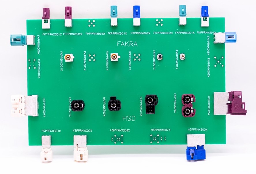
Fakra and HSD are industry standards managed by Rosenberger and widely used in automotive applications, they serve fundamentally different data-rate tiers and wiring philosophies. Understanding when to make the switch is crucial for balancing system performance and cost.
Signs You Need to Upgrade to HSD
- From Analog to HD Digital: If upgrading from old analog video (CVBS) to 1080p/4K displays (LVDS, APIX), FAKRA lacks the bandwidth. You need HSD.
- Space Constraints: If dashboard or door panel routing space is tight, one HSD cable replaces four bulky FAKRA lines, cutting weight and clutter.
- EMI/EMC Failures: If your high-speed links are failing automotive EMC compliance, HSD’s 360° full shielding resolves cross-talk and radiation issues.
Comparison Matrix:
| Feature | FAKRA Connectors | HSD Connectors |
|---|---|---|
| Internal Structure | Single Coaxial (1 Pin) | Quad-Core / Star Quad (4 Pins) |
| Max Data Rate | Typically lower (Optimized for RF/Analog) | Up to 6 Gbps+ (Digital High-Speed) |
| Common Protocols | Analog RF, GPS, Satellite Radio, CVBS | LVDS, GVIF, Ethernet (100BASE-T1), USB 2.0/3.0 |
| Cable Efficiency | 1 cable = 1 signal channel | 1 cable = 2 differential pairs (or Power + Data) |
| Size & Space | Larger footprint per channel | Compact; replaces up to 4 FAKRA lines |
5-Step Checklist for Automotive HSD Selection
1. Signal & Speed: Confirm it’s for high-speed digital data (LVDS/Ethernet, up to 6 Gbps), not analog RF.
2. Configuration: Choose 4-pin Star Quad layout based on your needs (Single/Dual pairs or Data+Power).
3. Coding: Select the exact mechanical coding (Code A, B, C, etc.) to prevent production misplugging.
4. Shielding: Use Fully Shielded near sensitive RF antennas (EMC compliance); use Semi-Shielded only in isolated, low-interference zones.
5. Environment: Match automotive-grade specs (IP waterproofing, up to 125°C temperature, and vibration locking) based on installation zones.
Related Post:
Key Differences Between Fakra Connectors and HSD Connectors?
HSD Cable Assembly and RF Testing Standards
Assembling an automotive-grade HSD harness requires precise manufacturing control; variations of fractions of a millimeter can severely degrade high-frequency performance. The production cycle follows strict multi-stage processes:
Core Manufacturing Safeguards
- High-Precision Stripping: Uses programmable rotary laser or specialized mechanical workstations to strip the outer jacket and dielectric, minimizing the risk of nicking the shield or core insulation. The outer braid is uniformly folded over the support sleeve to mitigate loose strands.
- Terminal Crimping: The four center pins are crimped using a synchronized 4-point or 8-point press, applying uniform radial force to achieve a gas-tight, low-resistance connection. After inserting the pins into the dielectric isolator, the outer metallic shield barrel is secured via a hexagonal or circular crimp die to ensure continuous 360° shielding.
Quality Assurance Protocols
- Mechanical Verification: Employs automated inline inspection to monitor pull-out force (tensile strength) alongside microscopic cross-sectional analysis of crimp height and width to verify proper compaction ratios.
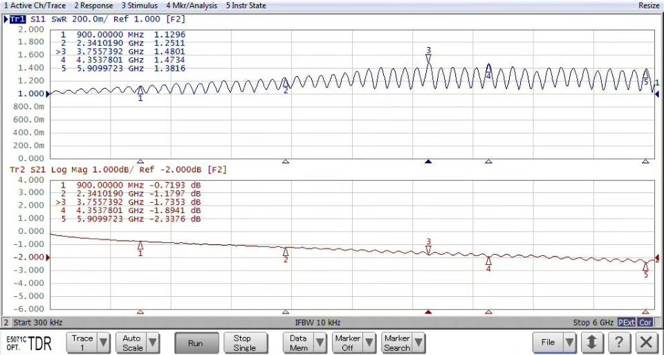
- RF Validation: Every batch is evaluated via a calibrated Vector Network Analyzer (VNA) to measure Scattering Parameters (S-parameters), ensuring Insertion Loss (S21) and Return Loss (S11) stay within strict limits up to 2 GHz.
- TDR Impedance Mapping: Time Domain Reflectometry (TDR) injects fast electrical pulses to map characteristic impedance along the cable. This detects local discontinuities caused by deformed shielding or poor crimping, locating faults with centimeter-level precision.
Related Products: HSD Cable
Common Mistakes to Avoid in HSD Assembly & Installation
- Violating Minimum Bend Radius:
The Pitfall: Bending a high-frequency Star Quad cable too sharply during vehicle routing deforms its internal geometry. This alters the physical distance between the core conductors and the outer shield.
Technical Impact: This mechanical distortion causes a local drop in characteristic impedance—often plunging from the nominal 100Ω down to 80Ω or lower. This creates an impedance discontinuity that reflects signal energy back to the source.
- Improper Housing Engagement and Latch Failure:
The Pitfall: Line technicians failing to ensure complete mechanical engagement of the plastic housing latches during field assembly.
Technical Impact: A partially mated connector degrades shielding continuity, introduces intermittent contact, and risks backing out entirely under vehicle vibration.
- Excessive Untwisting Length During Stripping:
The Pitfall: Technicians frequently untwist the four internal core wires beyond the manufacturer’s limit (strictly 3 to 5 mm max) when stripping the cable jacket to crimp center pins.
Technical Impact: Excessive untwisting destroys the balanced Star Quad geometry, creating a severe impedance discontinuity and spikes in near-end crosstalk (NEXT) that trigger VNA test failures.
Frequently Asked Questions (FAQ)
Q1: Are HSD connectors suitable for automotive Ethernet applications?
Certain HSD configurations can support high-speed differential protocols used in automotive networking systems. Actual compatibility depends on connector design, cable quality, transmission frequency, and OEM validation requirements.
Q2: Can Code Z (Water Blue) HSD connectors be used in mass production vehicles?
While technically possible, it is generally not recommended for final assembly lines. Code Z features a neutral mechanical keying that fits into any other color-coded socket. It is intentionally designed for R&D testing, diagnostics, and aftermarket maintenance to reduce tool changes, but lacks the specific error-proofing required to prevent mis-mating during fast-paced factory assembly.
Q3: How does the cable length affect the signal integrity of an HSD assembly?
As cable length increases, insertion loss naturally rises, which can degrade high-frequency signals like GMSL2 or FPD-Link III. For long cable runs across a vehicle chassis, hardware engineers must carefully select high-grade shielded cables with tightly controlled 100-ohm impedance and optimize the PCB-side equalization to maintain a stable data link.
HSD Connector Datasheet

Connectors & cable assemblies manufacturer.
Sharing insights on connectors and real-world applications.
Contact for datasheets, samples, or inquiries.
