In the complex ecosystem of modern wireless communications, telecommunications, and test environments, seamless signal transmission is paramount. Even the most sophisticated networking equipment is rendered ineffective if the physical connections fail to bridge the gap between different system components. This is exactly where the RF adapter becomes critical.
This comprehensive guide explores everything you need to know about RF adapters. From understanding the core definition and various RF adapter types to exploring specific RF adapter applications and the crucial parameters for selection, this guide will serve as your ultimate resource for navigating the world of coaxial interconnects.
What Is an RF Adapter?
An RF adapter (Radio Frequency adapter), also commonly referred to as a coaxial adapter, is a passive electromechanical device designed to connect two different or incompatible RF interfaces. Its primary function is to allow the seamless transition of radio frequency signals between different cables, connectors, or devices while maintaining the integrity of the signal.
At its core, a coaxial cable adapter consists of a metallic inner conductor, a dielectric insulator (such as PTFE/Teflon), and an outer metallic body that acts as both a shield and a ground. Adapters are manufactured to precise mechanical tolerances to ensure they do not introduce significant reflections or signal loss into the transmission line. Whether you are connecting a massive cellular base station to its antenna or linking a prototype PCB to a network analyzer, an RF adapter is the bridge that makes the physical connection possible.
Why RF Adapters Are Used
Engineers and technicians rely on the RF connector adapter for several vital operational reasons:
- Bridging Incompatible Interfaces: The most obvious use case is connecting two different connector types (e.g., an N-Type cable to an SMA port on a device) without having to splice or replace the existing coaxial cable infrastructure.
- Gender Conversion: RF connectors are gendered (male/plug and female/jack). When you have two male cables that need to meet, a female-to-female RF adapter acts as a gender changer, solving the immediate logistical problem.
- Equipment Protection (Connector Savers): High-end Test & Measurement equipment, such as Vector Network Analyzers (VNAs), feature highly precise and expensive output ports. Constant mating and unmating wear down these threads. Engineers use high-quality RF adapters as “connector savers”—sacrificial interfaces that take the physical wear and tear, protecting the expensive machinery.
- Impedance Matching: While most RF systems operate at 50 ohms, some industries (like CATV and broadcast video) utilize 75-ohm systems. Specific RF adapters are designed to bridge 50-ohm and 75-ohm systems with minimal reflection, although dedicated impedance matching pads are sometimes required.
- Space Management: In tight enclosures, right-angle adapters allow cables to turn 90 degrees without bending the coaxial cable past its minimum bend radius, preventing internal cable damage.
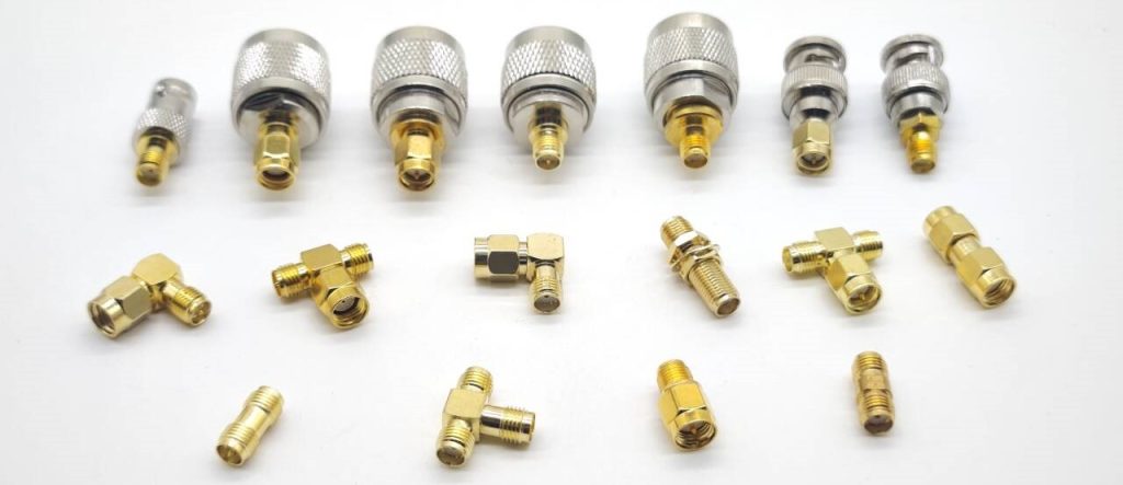
Common RF Adapter Types
The diversity of RF adapter types is vast, categorized primarily by their mechanical configuration, series compatibility, and physical geometry.
By Connector Compatibility
In-Series Adapters: These adapters feature the same connector series on both ends. They are primarily used for gender changing, extending cable lengths, or acting as connector savers. Typical examples include:
Between-Series Adapters: These feature different connector series on each end. They are the ultimate problem solvers when bridging disparate systems. Common configurations include:
- F to PAL
- SMA to N
- TNC to SMB
- FAKRA to SMA (commonly used when testing automotive antenna systems with laboratory RF instruments.)
By Geometry
Straight Adapters: The most common configuration, providing the shortest electrical path and lowest signal loss.
Right-Angle Adapters: These form a 90-degree bend, ideal for compact spaces and routing cables cleanly along equipment chassis.
T-Adapters (3-Way): Used to split or combine signals, featuring one input and two outputs (e.g., BNC Female to two BNC Males).
By Gender Configuration
Gender changers convert male interfaces to female interfaces or vice versa without changing the connector series. Examples include:
By Mounting Method
Bulkhead RF Adapters: They are designed for panel mounting and provide a secure RF connection through an enclosure wall or equipment housing. Typical applications include:
- Communication cabinets
- Test equipment
- Industrial control systems
- Outdoor RF enclosures
Common Connector Series
- SMA Adapters: SubMiniature version A. Extremely common in low-power, high-frequency applications (up to 18 GHz, or 26.5 GHz for precision versions). Used widely in Wi-Fi, IoT, and testing.
- BNC Adapters: Known for their quick connect/disconnect bayonet coupling. Limited to lower frequencies (usually below 4 GHz), heavily used in oscilloscopes and broadcast video.
- N-Type Adapters: Highly rugged and weather-resistant, capable of handling medium power. Excellent up to 11 GHz (sometimes 18 GHz). Standard in base stations and outdoor antennas.
- TNC Adapters: Similar to BNC but with threaded coupling for better stability in high-vibration environments (up to 11 GHz). Common in aviation and military.
- UHF Adapters: An older design primarily used in low-frequency applications (under 300 MHz) like ham radio and marine VHF.
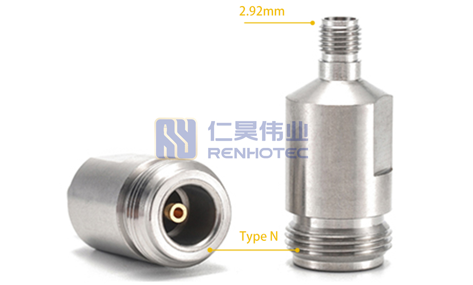
- Precision and Metric Adapters (e.g., 2.92mm, 2.4mm, 1.85mm): Designed for high-frequency millimeter-wave applications ranging from 40 GHz up to 67 GHz and beyond, depending on the connector series, utilized in aerospace and advanced 5G/6G R&D.
Note: While 2.92mm interfaces are mechanically compatible with standard SMA series, they cannot be mated with 2.4mm or 1.85mm series; doing so will result in immediate mechanical destruction of the precision inner contacts.
Common RF Adapter Applications
The versatility of the coaxial adapter makes it indispensable across a multitude of industries. To meet the specific mechanical and environmental demands of various sectors, manufacturers offer Industry-Specific RF Adapters engineered for targeted deployments:
- Telecommunications and 5G: Cellular base stations, DAS (Distributed Antenna Systems), and small cells rely heavily on N-Type, 4.3-10, and 7/16 DIN adapters to connect high-power RF transmitters to massive MIMO antennas. Low intermodulation distortion (PIM) is a critical requirement here.
- Test and Measurement: Laboratories equipped with VNAs, spectrum analyzers, and oscilloscopes utilize precision in-series and between-series adapters. These adapters are engineered for extreme repeatability, low insertion loss, and stable phase characteristics over high frequencies.
- Aerospace and Defense: Military radios, radar systems, satellite communications, and avionics often utilize RF adapters based on military-grade connector standards such as MIL-PRF-39012. These applications demand reliable performance under extreme temperatures, high vibration levels, and harsh environmental conditions, making threaded interfaces such as TNC and SMA common choices.
- Consumer Electronics and IoT: From smart utility meters to consumer Wi-Fi routers and GPS modules, miniature RF adapters (like U.FL to SMA) are frequently used to bridge small internal PCB connections with external antennas.
- Medical Equipment: MRI machines and other diagnostic equipment use RF signals for imaging, requiring non-magnetic coaxial adapters to prevent interference with the highly sensitive magnetic fields.

How to Choose the Right RF Adapter
Selecting the optimal RF connector adapter is not merely a matter of finding the right physical fit; it involves matching electrical and environmental specifications to the demands of your system. Here are the key selection factors:
A. Connector Interface and Coupling Mechanism
The mating interface determines how the adapter physically locks with corresponding connectors and severely impacts usability, vibration resistance, and installation speed.
- Standard vs. Reverse Polarity (RP): Crucial for wireless and Wi-Fi applications. Standard connectors have a center pin on the male plug, while RP (Reverse Polarity) variants swap the center contacts (male plug contains the receptacle). Mixing these up renders the adapter unusable.
- Coupling Mechanisms: Choose based on your operational environment. Threaded interfaces (e.g., SMA, N-Type, TNC) provide high mechanical retention and lower phase noise in high-vibration systems. Bayonet interfaces (e.g., BNC) offer rapid quarter-turn locking for test benches. Push-on/Snap-on interfaces (e.g., SMP, MCX) are ideal for high-density blind-mating or automotive data links where space prevents hand-tightening.
- Interface Grades: Production/commercial-grade interfaces use cost-effective dielectrics like PTFE, whereas instrument/precision-grade interfaces use precise air-dielectric alignments to ensure sub-millimeter concentricity for repetitive test-lab mating.
B. Frequency Range
Every RF adapter has a maximum operating frequency, often dictated by the internal dimensions of the connector and the dielectric material. Selecting an adapter whose cutoff frequency is lower than your system’s operating frequency will result in severe signal degradation. Always ensure the adapter is rated comfortably above your maximum operating frequency.
C. Impedance
Impedance mismatch causes signal reflection (return loss), which can damage transmitters and distort data. Ensure your adapter matches the system impedance. 50-ohm adapters are standard for data and communications; 75-ohm adapters are standard for video and CATV.
D. Mounting Style and Mechanical Configuration
Beyond electrical performance, how the adapter physically integrates into your system hardware is vital for mechanical stability and long-term reliability.
- Free-Hanging (In-Line): Has no external mounting features and is designed strictly to connect two cables in a suspended, inline configuration.
- Bulkhead Mount: Features an integrated locking nut and washer (often with an O-ring for weatherproofing). It allows the adapter to pass through an enclosure panel, securing internal routing to external cables.
- Flange Mount (2-Hole or 4-Hole): Utilizes a square or rectangular flange secured with screws. This provides maximum mechanical strength and prevents the adapter from twisting in high-vibration aerospace or military applications.
E. VSWR (Voltage Standing Wave Ratio) and Insertion Loss
- VSWR: A measure of how efficiently RF power is transmitted through the adapter. A perfect VSWR is 1.0:1. For most high-quality adapters, a VSWR of <1.20:1 at maximum frequency is desirable.
- Insertion Loss: The amount of signal power lost as it passes through the adapter, measured in decibels (dB). Precision adapters aim for insertion losses well below 0.1 dB or 0.2 dB.
F. Power Handling
Adapters have specific power ratings (in Watts) based on their size and heat dissipation capabilities. Large connectors like 7/16 DIN can handle kilowatts of power, whereas small SMA adapters may only handle a few hundred watts or less. Exceeding power limits can melt the dielectric.
G. Passive Intermodulation (PIM)
In modern telecom (4G LTE/5G), PIM is a massive concern. It occurs when two or more signals mix in non-linear components (often due to poor plating, magnetic materials, or loose connections), creating ghost signals that drown out real data. “Low-PIM” adapters, usually made with tri-metal or silver plating, are required for these applications.
H. Materials and Plating
- Body: Usually brass or stainless steel. Stainless steel is more durable for repetitive mating (test environments), while brass is easier to machine and cost-effective.
- Center Contact: Beryllium copper (BeCu) or phosphor bronze, plated with gold for superior conductivity and oxidation resistance.
- Dielectric: PTFE (Teflon) is standard due to its excellent electrical properties and high-temperature tolerance.
I. Environmental Ratings
If the adapter will be deployed outdoors on a cellular tower or marine vessel, it must be weather-resistant. Look for IP67 or IP68 ratings, indicating protection against dust ingress and water immersion.
Custom RF Adapter Solutions
While the market is flooded with standard off-the-shelf RF adapter types, cutting-edge projects often push the boundaries of standard components. This is where Custom RF Adapter solutions come into play.
Original Equipment Manufacturers (OEMs) and R&D facilities frequently partner with RF connector manufacturers to design bespoke solutions. Customizations can include:
- Unique Geometries: Designing specific sweep angles (e.g., 45 degrees) to fit tightly packed satellite housings.
- Phase Matching: For phased array radars and quantum computing, adapters can be custom-matched to ensure exact phase lengths across multiple transmission lines.
- Specialized Materials: Utilizing non-magnetic materials for medical applications, or specialized alloys for deep-space missions subjected to extreme radiation and thermal vacuum conditions.
- Integrated Flanges and Bulkheads: Custom mounting options to ensure hermetic seals in pressurized environments.
Working with a reliable manufacturer to design a custom coaxial cable adapter is engineered to minimize electrical degradation while adapting to your system’s unique mechanical constraints.
FAQ
Q1: Can I connect a 50-ohm adapter to a 75-ohm system?
Mixing 50-ohm and 75-ohm interfaces may lead to impedance mismatch, degraded signal performance, and, in certain connector series, potential mechanical compatibility issues. Always verify connector specifications before mating different impedance systems.
Q2: What is a “connector saver” RF adapter?
It is a high-precision, in-series adapter (e.g., SMA Male to SMA Female) attached permanently to the expensive port of test equipment (like a VNA). Users connect their cables to the adapter instead of the machine, so when the threads eventually wear out from repeated use, only the inexpensive adapter needs replacing, helping reduce wear on expensive instrument interfaces.
Q3: Does using an RF adapter cause signal loss?
Yes, every passive component inserted into an RF line introduces some degree of insertion loss and alters the VSWR. However, high-quality, precision RF adapters are engineered to keep this loss extremely minimal (often <0.1 dB), making it negligible for most practical applications.
Q4: How do I know the gender of my RF adapter?
In RF terminology, gender is determined by the center contact, not the outer threaded body. A connector with a center pin is Male (Plug), while a connector with a center receptacle (hole) is Female (Jack). Note: Reverse Polarity (RP) connectors flip this convention, which is common in Wi-Fi routers to comply with FCC regulations.

Connectors & cable assemblies manufacturer.
Sharing insights on connectors and real-world applications.
Contact for datasheets, samples, or inquiries.