Executive Summary
A leading domestic manufacturer of 800G/1.6T high-speed direct attach copper (DAC) cables required a robust interconnect solution for their continuous 7x24h automated testing facilities. Traditional RF test cables operating at 40GHz or 67GHz can no longer satisfy the bandwidth, phase stability, and durability required for next-generation PAM4 validation. This case study explains how Renhotec developed a custom High Frequency RF Cable and Precision RF Cable Assembly that enabled reliable DC–110GHz automated production testing while reducing annual RF testing costs by 40%.

Project Overview
Industry | AI Data Center Connectivity
Customer | Leading Manufacturer of High-Speed Direct Attach Copper (DAC) Assemblies
Application | Automated Signal Integrity Testing for 800G, 1.6T and Next-Generation 3.2T DAC Products
Testing Platform | 24/7 Multi-Port Vector Network Analyzer (VNA) Systems with RF Switch Matrices
Frequency Range | DC–110GHz High-Frequency RF Testing
The Challenge
High-Frequency Test Bottlenecks in the AI Era
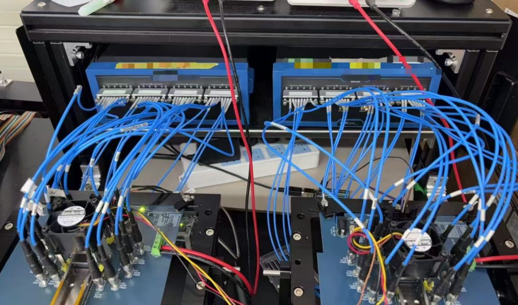
The client was expanding their multi-port Signal Integrity testing lines utilizing high-end Vector Network Analyzers (VNAs) and custom PCB switch matrices. They encountered critical roadblocks in testing next-generation high-speed copper cables:
- Bandwidth Limitations: Legacy flexible testing cables were capped at 40GHz to 67GHz. During the impedance and loss measurements for PAM4 encoded 1.6T and 3.2T configurations, error rates spiked. The existing setup failed to support the required 110GHz frequency range necessary to meet CEI 224G/448G and IEEE 802.3ck specifications.
- Rapid High-Frequency Degradation: Standard unarmored cables experienced severe phase drift, elevated return loss, and unacceptable Voltage Standing Wave Ratio (VSWR) after just 2 to 3 months of use (exceeding 500 daily mating cycles). This data distortion forced frequent VNA recalibrations, artificially lowering DAC production yield.
- Mechanical Vulnerability and High TCO: The dense wiring environment between switch matrices and test boards resulted in frequent cable crushing, pulling, and inner conductor fractures. With a lifespan of only 500 to 800 mating cycles, the constant replacement of conventional cables drove up the Total Cost of Ownership (TCO) and maintenance labor.
- Unpredictable Production Downtime: Hidden structural damage within unarmored cables led to sudden data failures mid-test. These unpredictable faults caused emergency line stoppages, creating bottlenecks in DAC validation and risking delivery schedules for global AI computing clients.
The Solution
Renhotec 1.0mm Armored RF Test Cables
Rather than simply replacing a higher-frequency cable, the customer required an RF interconnect capable of supporting long-term production reliability under demanding manufacturing conditions. The objective was not only to extend measurement bandwidth to 110GHz, but also to improve mechanical durability, minimize calibration drift, and reduce maintenance interruptions across an automated testing environment operating around the clock.
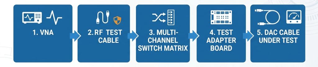
After evaluating the requirements of the production system, the customer standardized on the Renhotec 1.0mm Male-to-Female 110GHz Armored RF Test Cable as the RF interconnect between the vector network analyzer (VNA), RF switch matrix, and customized PCB test fixtures. The solution combined high-frequency electrical performance with reinforced mechanical protection, enabling the testing platform to support both current production programs and future AI interconnect development.
Expanding to DC–110GHz
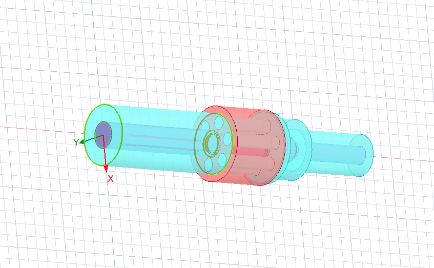
The first design objective was to eliminate the bandwidth limitations of the previous RF test cables. Equipped with precision 1.0mm male and female RF connectors, the cable assembly supports a continuous operating frequency range from DC to 110GHz, allowing a single test cable to accommodate both current 800G and 1.6T production programs as well as future 3.2T development projects.
This broader frequency coverage allows manufacturers to consolidate multiple cable specifications into one standardized solution, simplifying inventory management while ensuring compatibility with evolving signal integrity requirements. More importantly, stable electrical characteristics across the full operating range provide engineers with greater confidence when evaluating insertion loss, return loss, crosstalk, and other critical high-frequency parameters during production testing.
Armored Protection
Electrical performance alone cannot guarantee reliable production testing.
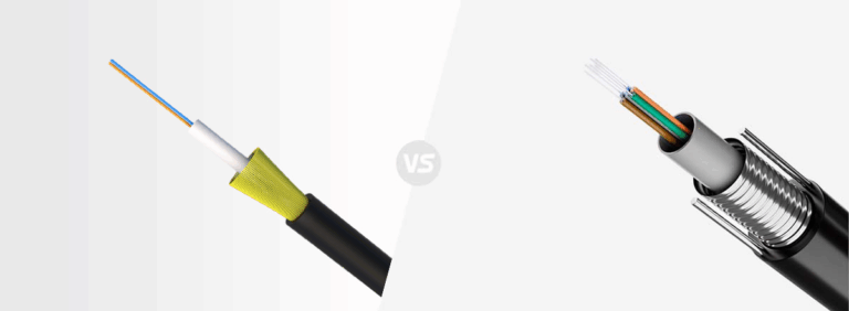
In automated manufacturing environments, RF test cables are continuously routed through densely populated switch matrices and repeatedly subjected to bending, compression, and abrasion. To address these conditions, the cable incorporates an integrated metal armored protective layer surrounding the cable body.
Unlike conventional flexible RF assemblies, the armored structure significantly improves resistance to crushing, repeated flexing, and accidental mechanical damage without compromising routing flexibility inside complex testing systems. By protecting the internal conductor structure from external stress, the cable maintains consistent electrical performance over a substantially longer operating life while reducing unexpected failures caused by physical wear.
Increasing Connector Life
Another critical consideration was connector durability. Because each testing station performs hundreds of mating cycles every day, connector wear gradually becomes a major contributor to measurement instability.
The cable utilizes precision gold-plated beryllium copper contacts engineered for more than 2,000 mating cycles, extending connector life to more than twice that of conventional production test cables. This improvement not only reduces replacement frequency but also helps maintain consistent contact resistance throughout prolonged production operation. For high-volume manufacturing, longer connector life directly translates into lower maintenance requirements and fewer interruptions caused by routine cable replacement.
Stable Measurements
Modern AI interconnect production depends heavily on measurement consistency. Even small variations in phase or insertion loss can trigger unnecessary recalibration or create uncertainty during signal integrity evaluation.
To improve long-term measurement stability, the cable adopts a low-loss, phase-stable dielectric structure optimized for continuous high-frequency operation. This design minimizes amplitude and phase drift throughout extended production cycles, allowing the VNA system to maintain reliable measurement accuracy over longer operating periods. As a result, calibration intervals can be extended, helping engineering teams spend less time maintaining test equipment and more time supporting production throughput.
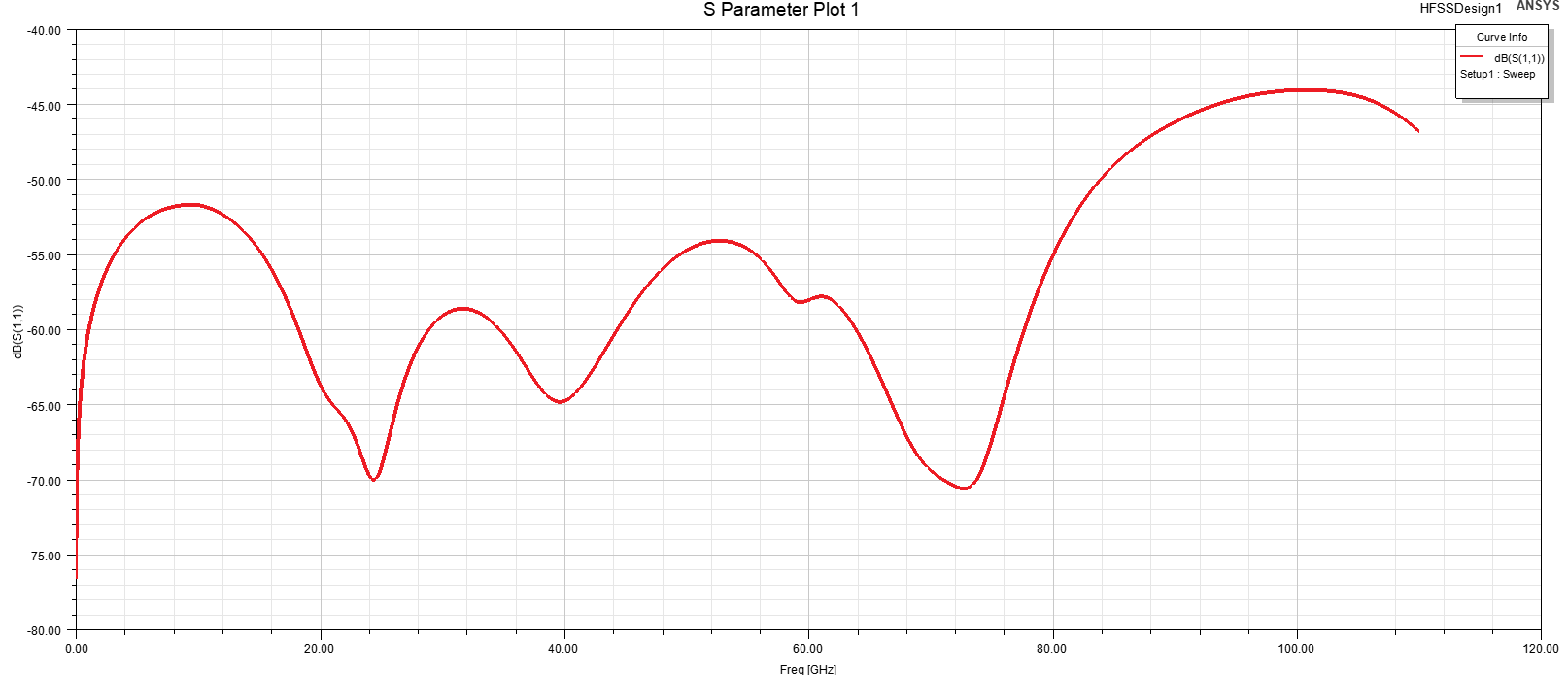
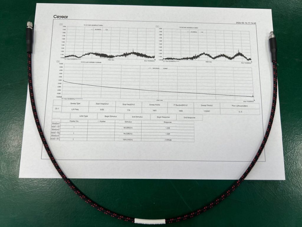
Technical Performance Validation
These engineering validations provided the customer with confidence that the cable could be deployed as a standardized RF interconnect throughout its automated production line.

Project Outcomes
40%
Reduction in annual RF testing consumable expenditures
DC-110GHz
Full validation coverage for legacy 800G/1.6T and next-gen 3.2T DAC bandwidth
7+ Months
Average Cable Service Life
The operational shift delivered immediate dividends to the corporate balance sheet. By extending the average cable retirement cycle from 3 months to over 7 months, the factory slashed its annual RF testing consumable procurement expenses by 40%, while significantly reducing technical labor hours spent on constant system recalibrations.
On the manufacturing floor, the eradication of unpredictable cable failures stabilized overall equipment effectiveness (OEE), maximizing daily throughput. Ultimately, by consolidating their entire testing workflow onto a single, universal VNA Test Cables platform, the client eliminated fragmented inventory SKUs, streamlined their components supply chain, and solidified their capacity to scale alongside the global AI infrastructure curve.
Contact us
As AI computing scales toward 1.6T and 3.2T interconnects, production test environments must evolve to handle laboratory-grade frequencies in punishing, high-volume industrial settings. By replacing standard flexible test leads with Renhotec’s 110GHz Armored Test Cables, the customer successfully bridged the gap between cutting-edge electrical requirements and rigorous mechanical durability. The transition not only secured compliance with next-generation IEEE standards but fundamentally improved the commercial efficiency of their manufacturing floor.
Looking for a reliable RF test solution for your production environment?
Looking for a Customized RF Testing Solution?

Connectors & cable assemblies manufacturer.
Sharing insights on connectors and real-world applications.
Contact for datasheets, samples, or inquiries.