
Why Are FAKRA Connectors Usually Delivered Unassembled?
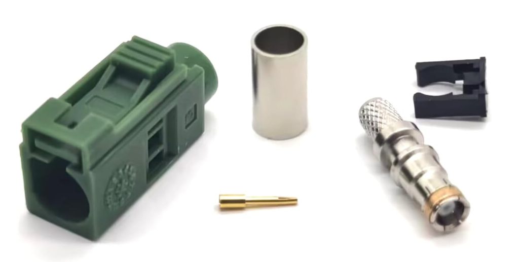
Recently, a client reached out to me because they had ordered a bulk shipment of FAKRA connectors for an upcoming automotive telematics project. However, upon opening the boxes, they didn’t find ready-to-plug cables. Instead, they found a “Component Kit”—hundreds of tiny center pins, brass bodies, metal ferrules, and colored plastic housings scattered across different bags. They felt completely overwhelmed and asked, “Where is the manual? How do I even begin a FAKRA connector assembly?”
If you find yourself in the same situation, take a deep breath. This is entirely normal in the automotive and RF industry. FAKRA connectors are almost always delivered unassembled to allow manufacturers flexibility in cable routing, length customization, and precision crimping. This guide will walk you through the entire FAKRA cable assembly guide, from decoding the mechanical keying to mastering the crimping process.
FAKRA Coding and Mechanical Keying
Before we dive into how to install FAKRA connector components, you must understand their most defining feature: the mechanical and color-coding system.
The Role of Coding
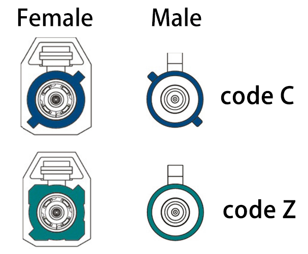
FAKRA stands for Fachkreis Automobil (Automobile Expert Group). To prevent miswiring on complex vehicle assembly lines, the FAKRA standard (DIN 72594-1 / USCAR-18) utilizes a foolproof color and mechanical keying system.
Common FAKRA Codes & Applications
| FAKRA Code | Color | Common Automotive Application |
|---|---|---|
| Code A | Jet Black | AM/FM Radio |
| Code B | Cream White | Phantom Radio Supply |
| Code C | Signal Blue | GPS / GNSS / Telematics |
| Code D | Bordeaux Violet | Cellular / GSM |
| Code E | Leaf Green | TV Type 1 |
| Code H | Heather Violet | GPS / Telematics |
| Code Z | Water Blue | Universal (Mates with all codes) |
Mechanical Anti-Error Mechanism
FAKRA connectors are specifically designed to mechanically prevent mis-mating between different codes (e.g., attempting to connect a Code A plug into a Code B jack). The secret lies inside the plastic housing. Each code features a unique physical arrangement of internal ribs and slots (the FAKRA connector pinout structure). If you try to mate mismatched connectors, these plastic ribs will clash, preventing the internal RF contacts from ever touching.
The Exception: Code Z (Water Blue)
Code Z is the “master key.” Its internal plastic housing lacks the restrictive ribs found in other codes, allowing it to mate with any other FAKRA connector (A through N). It is highly useful for testing, diagnostics, or temporary aftermarket repairs.
Choosing the Right FAKRA Connector Before Assembly
Success in FAKRA connector assembly begins before you pick up a tool. You must ensure your components match your system requirements.
1. Cable Compatibility (The Biggest Trap)
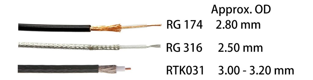
The most common installation mistake is pairing a FAKRA connector with the wrong coaxial cable. The internal brass body and ferrule are manufactured to exact tolerances based on the cable’s outer diameter and dielectric size.
- RG174 & RG316: Standard flexible cables for short automotive runs.
- RTK031: Often used for high-frequency applications like camera systems due to lower signal loss.
- Note: A FAKRA Connector designed for RG174 may deform the dielectric and compromise the 50-ohm impedance of an RTK031 cable.
2. Coding Selection
Match the FAKRA code strictly to the device you are building. Using a universal Code Z in final production is generally frowned upon by automotive OEMs, as it bypasses the safety mechanism intended to prevent line workers from plugging the GPS antenna into the cellular modem.
3. Straight vs. Right-Angle
Review your spatial constraints. Right-angle FAKRA connectors save space behind dashboards but are slightly harder to crimp and may introduce a marginal amount of signal loss compared to straight connectors.
4. Waterproof / Automotive Grade
If the connection lives outside the cabin (e.g., side mirrors, shark fin antennas), ensure you select sealed FAKRA connectors featuring internal O-rings and specific waterproof housings (IP67/IP69K).
Related Post: FAKRA Connector Selection Guide
Main Components of a FAKRA Connector
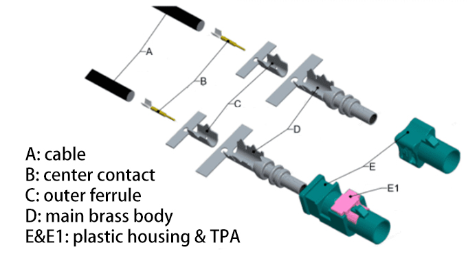
Whether you purchase Code A or Code N, when you open the bag, you will typically find four distinct loose parts. Inform your line workers or technicians that they must assemble these on-site:
- Center Contact (Pin or Socket): The tiny gold-plated pin that carries the core signal.
- Main Brass Body (with Dielectric Insulator): The heavy metal housing that provides RF shielding and houses the insulator.
- Outer Ferrule: A small metal tube used to secure the cable’s braided shield to the brass body.
- Plastic Housing & TPA: The colored outer shell that provides the mechanical coding, usually paired with a secondary lock (Terminal Position Assurance / TPA).
Tools Required for Assembly
Attempting how to crimp FAKRA connector components with standard household pliers is a recipe for disaster. You need specialized tools for standard 50 Ohm RF connections:
- Coaxial Cable Stripper: Capable of making precise 2-step or 3-step cuts.
- Micro Crimp Tool (for Center Pin): Often requires a specific die-set for sub-miniature pins.
- Hex Crimp Tool (for Outer Ferrule): Must match the exact hex size of the FAKRA ferrule (e.g., 3.25mm hex for RG174).
- Heat Shrink Tubing & Heat Gun: (Optional but recommended for strain relief).
Tired of complex assembly & high defect rates from manual crimping?
Get factory-overmolded, 100% HF-tested automotive cable harnesses. Get a Quote / Free Sample Now!
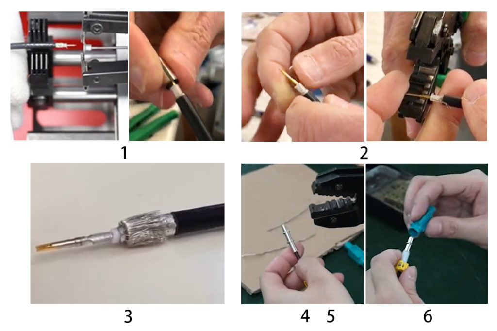
Step-by-Step Installation (Connector-to-Cable)
Here are the standard FAKRA connector installation steps. (Always cross-reference with your specific manufacturer’s datasheet for exact strip dimensions).
Step 1: Strip the Cable
Slide the outer metal ferrule onto the cable first. Use your coaxial stripper to remove the outer jacket, braided shield, and inner dielectric according to the manufacturer’s specified dimensions. You should now see the exposed inner copper core.
Step 2: Crimp the Center Contact
Place the gold center pin over the exposed inner conductor. Ensure the conductor is visible through the tiny inspection hole on the pin. Use your micro-crimper to secure it. Do not solder unless specifically required by the manufacturer, as excess solder alters RF impedance.
Step 3: Flare the Braided Shield
Carefully fan out the metal braided wire shield so it resembles a skirt. Do not damage the inner foil shield if your cable has one.
Step 4: Insert the Main Body
Slide the main brass RF body over the inner dielectric until it snaps over the crimped center pin. The flared braided shield should go over the knurled tail of the brass body.
Step 5: Crimp the Ferrule
Slide the metal ferrule up so it covers the braided shield and clamps over the knurled tail of the brass body. Use your Hex Crimp tool to crush the ferrule firmly into place. This is called FAKRA crimping.
Step 6: Snap into the Plastic Housing
Insert the entire metal assembly into the colored plastic FAKRA housing until you hear a distinct “click.” Finally, push in the secondary lock (TPA) to secure the assembly permanently.
Key Assembly Parameters and Crimp Specifications
Once installed, technicians always ask: “Did I crimp this right?” Maintaining stable RF performance requires strict quality control over your FAKRA crimping process.
| Assembly Parameter | Importance | Typical Target (varies by cable) |
|---|---|---|
| Strip Length Accuracy | Dictates impedance and mechanical fit. | Core: ~2.5mm, Dielectric: ~1.5mm, Braid: ~3.0mm |
| Crimp Height (Pin) | Prevents signal degradation and pin failure. | Must meet manufacturer gauge (e.g., 0.85mm). |
| Pull Force (Pin) | Ensures the wire won’t pull out under vibration. | > 10 Newtons |
| Pull Force (Ferrule) | Ensures the cable jacket/shield won’t detach. | > 50 Newtons |
| Impedance Matching | Prevents RF wave reflection (VSWR issues). | 50 Ohms (Requires clean, uncrushed dielectric). |
Common Installation Mistakes
Avoid these frequent common FAKRA installation mistakes that lead to system failures:
- Secondary Lock (TPA) Not Fully Engaged: If the purple/colored lock isn’t pushed down completely flush with the housing, the connector will likely vibrate loose inside the vehicle.
- Poor Crimp Causing Signal Attenuation: Over-crimping the ferrule crushes the inner dielectric, altering the 50 Ohm impedance and causing massive RF signal loss (especially critical for high-speed camera data).
- Forced Mating (Breaking the Housing): Trying to force a Code A into a Code C jack by breaking the plastic ribs. This destroys the structural integrity of the connector.
- Forgetting to Put the Ferrule on First: Stripping the cable and crimping the center pin and brass body, only to realize you forgot to slide the outer metal ferrule onto the cable beforehand.
Frequently Asked Questions (FAQ)
How to remove a FAKRA connector? (FAKRA Connector Disassembly)
To perform FAKRA connector disassembly, you first need to disengage the secondary lock (TPA) using a small flathead screwdriver. Once the TPA is popped up or removed, locate the primary latch on the plastic housing. Depress it, and gently pull the metal body backward out of the plastic shell. Note: The crimped metal ferrule and center pin cannot be non-destructively removed from the wire.
Can FAKRA connectors be reused?
The plastic housings can sometimes be reused if removed carefully without breaking the internal retaining clips, but the metal crimp components (center pin and ferrule) are strictly single-use. Once crimped onto a coaxial cable, they cannot be un-crimped or reused without damaging the metal and the wire core.
Can I crimp a FAKRA connector without an official tool?
Technically yes, but practically no. Using standard household pliers instead of a dedicated hex crimp die will create an uneven crush on the ferrule. This ruins the 50-ohm RF shielding geometry and drastically reduces pull-force strength, leading to dropped GPS signals or blank camera feeds.
FAKRA vs. SMB connector: What is the difference?
A FAKRA vs SMB connector comparison is straightforward: FAKRA connectors utilize a modified SMB connection inside. The primary difference is that FAKRA wraps that standard metal SMB connector in a rigid, color-coded, mechanically keyed plastic housing specifically designed to handle the harsh vibrations and anti-error requirements of automotive environments.
What cables are compatible with FAKRA connectors?
FAKRA connectors are generally designed for standard 50-ohm coaxial cables with an outer diameter between 2.5mm and 3.2mm. The most common compatible cable types include RG174, RG316, RTK031, and LMR100.
Contact Us
Mastering how to install FAKRA connector components may seem daunting at first due to the loose parts and tight tolerances. However, once you understand the mechanical coding system and respect the precision required for stripping and crimping, the process becomes highly repeatable. Although FAKRA assembly is not highly complex, maintaining stable RF performance still requires proper tooling, cable compatibility, and correct crimp control.
Are you looking to source high-quality, automotive-grade FAKRA components or pre-assembled FAKRA cables for your next telematics project? We offer FAKRA connectors, Mini FAKRA solutions, and custom RF cable assemblies for GPS, antenna, camera, and telematics systems. Contact our team [email protected] for technical support, samples, or product recommendations.

Connectors & cable assemblies manufacturer.
Sharing insights on connectors and real-world applications.
Contact for datasheets, samples, or inquiries.
