
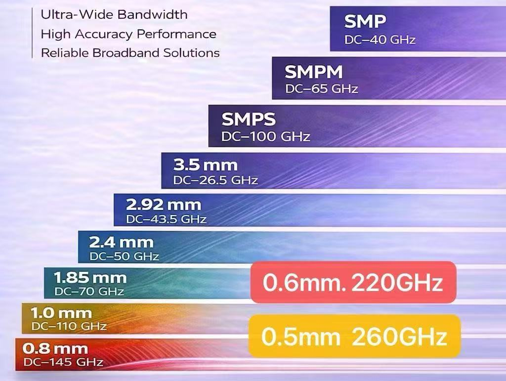
As 5G networks rollout, radar platforms evolve, and next-generation 6G research pushes into sub-terahertz (Sub-THz) frequency bands, hardware engineers face tough interconnect challenges. While established millimeter-wave (mmWave) standards like 2.92 mm (43.5 GHz) and 1.0 mm (110 GHz) meet the needs of today’s high-frequency test systems, pushing coax performance beyond 110 GHz requires overcoming strict physical limits.
Choosing a high frequency RF connector for ultra-broadband testing or Sub-THz prototyping involves balancing frequency range against mechanical tolerances, transmission loss, and board-level integration.
This guide breaks down the physical factors limiting coaxial performance above 110 GHz, compares mmWave connectors with waveguides, and highlights ultra-precision 0.8 mm, 0.6 mm, and 0.5 mm interfaces alongside high-density multi-channel solutions.
What Limits Coaxial Connector Performance Above 110 GHz?
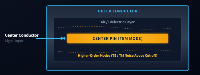
Coaxial transmission lines rely on TEM (Transverse Electromagnetic) wave propagation, keeping electric and magnetic fields perpendicular to the line of propagation. As operating frequencies rise into the mmWave and Sub-THz domains, the electromagnetic wavelength approaches the physical dimensions of the coaxial interface.
Higher-Order Modes and Cut-off Frequency
When the signal wavelength matches the circumferential dimensions of the dielectric gap, higher-order non-TEM modes (such as TE11) begin to propagate. This threshold is the cut-off frequency. Operating above this point causes severe resonance, phase distortion, and unpredictable signal loss. To raise the cut-off frequency, the physical dimensions of the connector’s outer conductor and center pin must be scaled down.
In simple terms, a coaxial connector is designed to carry one predictable signal mode. When the operating frequency becomes too high, additional electromagnetic paths appear inside the connector, causing phase errors and signal distortion.
Key Challenges: Modes, Loss and Impedance Continuity
At frequencies above 110 GHz, sub-millimeter manufacturing defects disrupt signal integrity:
- Center Pin Offset & Air Gaps: Microscopic misalignments or internal air gaps generate sudden impedance drops, causing high reflection (return loss).
- Dielectric Stepping: Transitions between air dielectrics and internal support beads act as capacitive discontinuities, creating unwanted signal reflections.
- Surface Roughness & Skin Effect: Higher frequencies concentrate current along the outer skin of the conductor (the skin effect). Surface roughness increases path length, significantly raising conductor attenuation.
- Plating & Torque Sensitivity: Variations in plating thickness or over-torquing during mating can deform the sub-millimeter center pin, ruining mechanical repeatability and causing permanent damage.
Choosing the Right Millimeter-Wave Connector
To simplify interface selection across standard mmWave connectors and experimental Sub-THz interfaces, the table below maps frequency capabilities, connector construction, and typical application scenarios:
| Interface | Typical published range | Connector type | Typical use |
|---|---|---|---|
| 3.5 mm | DC–26.5 GHz | Threaded precision coax | General microwave testing |
| 2.92 mm | DC–40 GHz; selected designs to 43.5 GHz | Threaded precision coax | 5G, radar and test systems |
| 2.4 mm | DC–50 GHz | Threaded precision coax | Higher-frequency instruments |
| 1.85 mm | DC–67/70 GHz | Threaded precision coax | V-band and high-frequency testing |
| 1.35 mm | DC–90 GHz | Threaded precision coax | E-band measurement |
| 1.0 mm | DC–110 GHz | Threaded precision coax | W-band and broadband measurement |
| 0.8 mm | Typically to 145 GHz | Precision coax | D-band and advanced testing |
| 0.6 mm | To approximately 220 GHz | Flange-based coax | Broadband Sub-THz measurement |
| 0.5 mm | Emerging systems to approximately 260 GHz | Ultra-precision coax | Advanced Sub-THz research |
*Frequency limits vary by manufacturer, connector construction, cable, PCB launch and complete system design.
Do You Still Need Coaxial Connectors Above 110 GHz?
As system requirements cross 110 GHz, engineers must choose between precision coaxial interconnects and rectangular waveguides:
| Factor | Precision coaxial | Waveguide |
|---|---|---|
| Bandwidth | Broadband | Band-limited |
| Connection | Compact and familiar | Flanged and mechanically larger |
| Loss | Increases rapidly at extreme frequencies | Often lower within its band |
| Calibration | Suitable for broadband VNA workflows | Requires band-specific components |
| Application | Broadband component testing | High-frequency band-specific systems |
While rectangular waveguides offer lower insertion loss for narrow, band-specific designs, precision coaxial solutions remain essential for broadband measurement setups, vector network analyzers (VNAs), and modular high-density platforms.
Our engineering team provides precision RF connectors and cable assemblies
Need technical guidance, custom pin configurations, or product datasheets?
How Sub-THz Connectors Push RF Performance Further?
Operating near the physical limit of coaxial transmission requires specialized interfaces designed for Sub-THz applications:
- 0.8 mm Precision Coax (90–145 GHz): Optimized for D-band millimeter-wave integration, 0.8 mm interfaces provide stable electrical performance, high repeatability, and low reflection for precision test benches.
- 0.6 mm Sub-THz Interfaces (Up to 220 GHz): Designed for Sub-THz R&D, 0.6 mm flange-based coax systems prioritize strict modal control and impedance continuity to prevent higher-order mode resonance near 200 GHz.
- 0.5 mm Emerging Sub-THz Solutions (Up to 260 GHz): Representing the current frontier of coaxial interconnect technology, 0.5 mm ultra-precision interfaces support advanced system-level research and next-gen experimental platforms operating near theoretical coax limits.
Note: 0.6 mm and 0.5 mm sub-millimeter interconnects are non-standardized, laboratory-grade products developed primarily for advanced R&D, prototype validation, and technical collaboration.
When Size Matters: SMPM and SMPS Solutions for High-Density
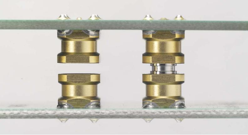
When designing high-density RF front-ends, phased-array radar, or modular test instrumentation, standard threaded mmWave connectors are often too large. Blind-mate push-on architectures like SMPM and SMPS address extreme space constraints while maintaining high-frequency performance:
[Dense Array PCB] ---> [SMPS/SMPM Interface] <=== Phase-Matched Cable ===> [RF Front-End]To maintain signal integrity in multi-channel designs, systems must control channel-to-channel phase consistency. Matching connector geometries, controlling cable electrical length, and maintaining tight assembly tolerances ensure identical phase tracking across array channels.
Multi-Channel Push-On Interface Options
| Interface | Recommended Performance & Application |
|---|---|
| SMP | Typical solutions up to 40 GHz |
| SMPM | Commonly 40–65 GHz, depending on configuration |
| SMPS | Commonly up to 65 GHz; selected precision designs may extend higher |
| Specialized high-density interfaces | Up to 100/110 GHz depending on validated design |
Building a Complete High-Frequency RF Signal Chain
Even the highest-grade high frequency RF connector will fail if paired with unstable cabling or an unoptimized PCB launch.
Phase-Stable Cable Assemblies for Precision Testing
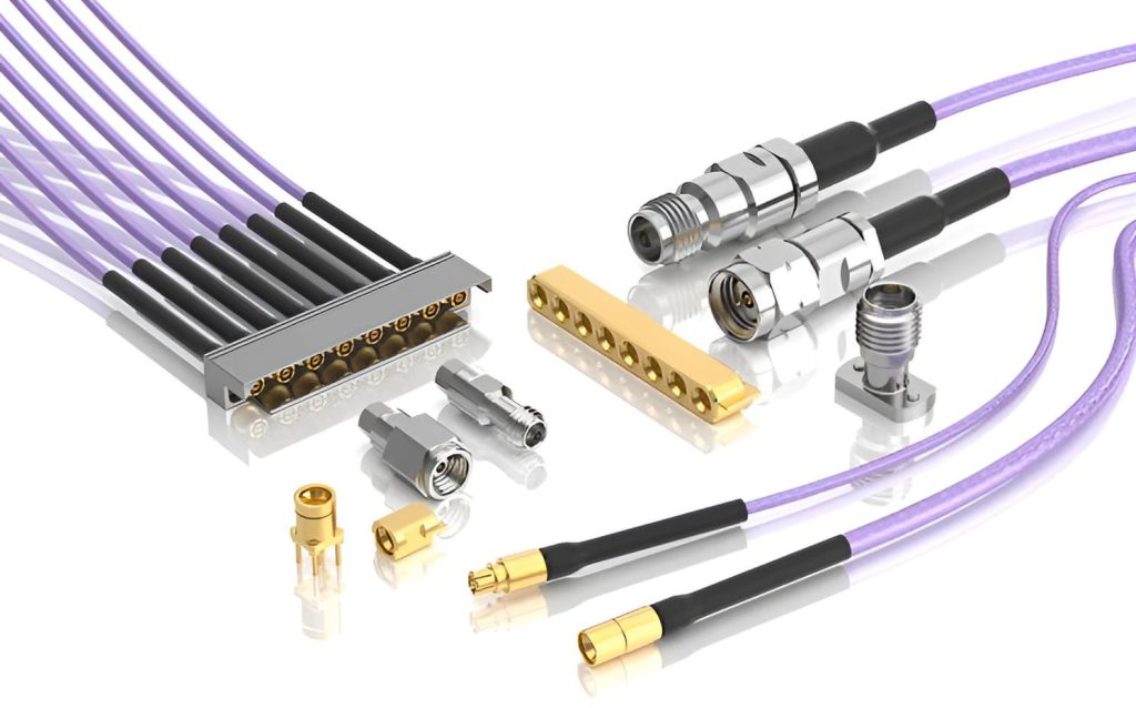
Precision VNA testing and wafer probers rely on cable assemblies that maintain amplitude and phase stability during movement. Phase drift caused by cable flexure introduces calibration errors, requiring frequent recalibration.
For demanding test environments, reinforced or armored outer jackets protect against mechanical stress, over-bending, and crushed dielectrics without sacrificing flex accuracy.
PCB Launch Design for High-Frequency Connectors
Bridging a high-frequency signal from a coaxial connector to a planar PCB trace introduces return loss risks:
- Solderless End-Launch Connectors: Clamped mechanically to the board edge, these connectors eliminate soldering heat variation, allow easy reuse, and optimize grounding on high-frequency substrates (such as Rogers or PTFE laminate).
- Surface-Mount (SMT) Transitions: Suitable for compact production layouts, but require precise ground-signal-ground (GSG) land pattern design and strict solder-stencil control to minimize parasitic inductance at the pad transition.
High Frequency RF Interconnect Solutions We Provide
Beyond individual RF connectors, we provide complete interconnect solutions including miniaturized interfaces, precision cable assemblies, and PCB integration solutions for high-frequency testing, measurement, and advanced RF systems.
01
Miniaturized & Multi-Channel RF Interconnect Solutions
Compact RF interconnect solutions designed for high-density systems, multi-channel architectures, and space-constrained RF applications.
- SMPM and SMPS interface solutions
- Multi-channel RF integration
- Phase consistency control
02
Precision RF Cable Assemblies & Components
High-performance RF cable solutions developed for precision measurement systems requiring phase stability and mechanical reliability.
- Phase-stable RF cable assemblies
- High mating repeatability
- VNA and RF test applications
03
RF & PCB Interconnect Solutions
Reliable RF connector and PCB interface solutions for testing equipment, communication systems, and RF system integration.
- SMA, 2.92mm, 2.4mm and 1.85mm interfaces
- PCB mount and end-launch configurations
- RF testing and system integration
Frequently Asked Questions
Why does a 110 GHz connector not guarantee a 110 GHz PCB transition?
A connector’s rating reflects its standalone coaxial performance. Once mounted to a circuit board, the total bandwidth depends on the entire signal path—including the PCB substrate’s dielectric constant, trace geometry, via stubs, launch impedance matching, and manufacturing tolerances. An unoptimized PCB transition can degrade a 110 GHz connector’s performance down to 40 GHz.
What is a millimeter-wave RF connector?
A millimeter-wave (mmWave) RF connector is a precision coaxial interconnect designed to transmit signals with wavelengths from 10 mm down to 1 mm (typically covering 30 GHz to 300 GHz). Examples include 2.92 mm, 2.4 mm, 1.85 mm, 1.0 mm, and sub-millimeter 0.8 mm interfaces.
Why are Sub-THz connectors smaller than conventional RF connectors?
Sub-THz connectors use smaller dimensions to raise the coaxial TE11 higher-order mode cut-off frequency. Shrinking the inner diameter of the outer conductor and center pin prevents modal resonance, ensuring stable, single-mode TEM signal transmission up to 220 GHz and 260 GHz.
Need Custom Interconnect Solutions?
Whether you need phase-stable VNA test cable assemblies, high-density SMPS multiport modules, or precision coaxial connectors for 5G and radar systems, our engineering team is ready to help.

Connectors & cable assemblies manufacturer.
Sharing insights on connectors and real-world applications.
Contact for datasheets, samples, or inquiries.
