
A cable and a connector housing are only the starting point of an HSD cable assembly. For samples, prototypes, low-volume orders, or urgent requirements that call for a quick response, manual assembly can offer a practical solution. The process involves preparing the cable, terminating the contacts, handling the shielding, and assembling the connector components in the correct sequence.
Each step matters. Incorrect wire positioning, poor crimping, or an improperly seated housing can affect the finished assembly and lead to additional inspection or rework.
So, how is an HSD connector assembled in practice? In this guide, we walk through the assembly processes for 4-pin and 4+2 HSD connectors, from cable preparation and contact crimping to housing installation and final inspection.
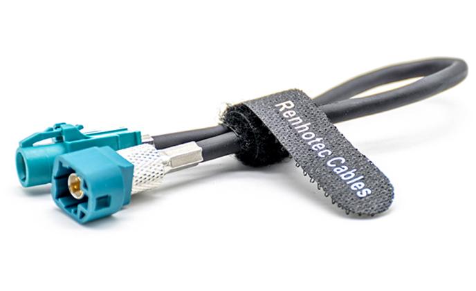
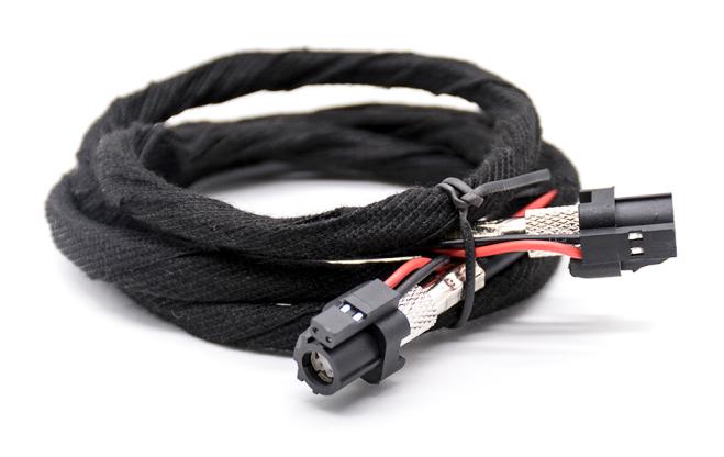
Looking for HSD components or pre-assembled cables?
Explore our HSD connector and cable assembly options.
1. Tools and Materials Required for HSD Connector Assembly
Before starting the assembly process, prepare the connector components, compatible cable, and appropriate tooling.
Typical items include:
- HSD connector housing and internal insulation components
- Contact pins or terminals
- Compatible shielded cable
- Metal ferrules or crimp sleeves, as applicable
- Cable stripping tools
- Contact crimping tools
- Ferrule crimping tools
- Assembly drawings and conductor-position references
- Inspection tools required by the applicable production specification
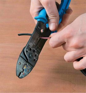
2. 4-Pin HSD Connector Assembly Instructions
The 4-pin HSD assembly process includes cable stripping, contact crimping, conductor positioning, contact insertion, and ferrule crimping. Follow the approved assembly drawing to maintain the correct conductor arrangement and mechanical fit.
Step 1Identify the Connector Components
Identify the male or female connector components before assembly. The reference procedure shows the connector body, insulation component, and contact pins as separate parts.


Step 2Prepare and Strip the Cable
Strip the cable jacket, inner conductors, and shielding according to the recommended cable stripping dimensions for the specific configuration.

Step 3Insert and Crimp the Contact Pins
Insert each prepared conductor into its corresponding contact pin and crimp it using the specified crimping tool.

Step 4Arrange the Conductors in the Correct Positions
Position the four conductors according to the approved connector wiring diagram.
Do not assume that conductor colors alone determine the correct pin assignment. If the cable uses different colors, follow the approved wiring diagram and verify the contact positions at both ends.

Step 5Insert the Contacts into the Insulation Component
Insert the prepared contacts into the corresponding positions in the insulation component.
Check that each contact is correctly positioned and that the insulation component is not damaged during insertion. Do not force the parts together if their alignment is incorrect.

Step 6Position the Cable and Crimp the Ferrule
Position the prepared cable assembly inside the connector body according to the assembly drawing. The reference shows the guiding feature aligned with the internal locating feature of the metal body before the cable is fully seated.
Next, crimp the ferrule using the designated tooling. The supplied reference illustrates a visible crimp indentation on the completed ferrule for both male and female HSD connectors.


Need the HSD Connector Specifications?
Refer to the product datasheet for connector dimensions, interface details, and applicable assembly requirements.
3. 4+2 HSD Connector Assembly Instructions
The 4+2 HSD configuration shown in the supplied assembly reference uses a different internal arrangement and additional housing and locking components. Its assembly sequence should therefore be followed separately rather than treated as identical to the 4-pin procedure.
Step 1Cut and Prepare the Cable
Cut the cable to the length specified in the production drawing.
The supplied 4+2 assembly reference indicates a cutting dimension of 13 ± 0.5. The unit and the precise measurement reference should be confirmed before this value is used in production.
Prepare the cable end according to the specified stripping and shielding requirements. Keep the exposed conductors organized to support correct terminal termination and subsequent housing installation.

Step 2Prepare the Shielding and Inner Conductors
Process the cable jacket and braided shielding according to the assembly drawing. Expose the conductors to the required lengths without damaging their insulation.
Keep the prepared conductors in the correct order and confirm that the shielding is positioned as required for the metal termination components.
The stripping and shielding preparation for this configuration should follow its own approved dimensions rather than automatically reusing the 4-pin dimensions.


Step 3Crimp the Terminals and Position the Contacts
Insert the conductors into the corresponding terminals and complete the specified crimping operation.
Use the designated tooling and verify that the contacts are correctly terminated before proceeding. Check the terminal arrangement against the applicable pin assignment.
The contact positions and conductor arrangement should be verified independently for the 4+2 configuration.


Step 4Insert the Contacts into the Insulation Component
Insert the crimped contacts into their designated positions in the insulation component.
For assemblies with different conductor colors or wiring arrangements, use the approved pin-position drawing rather than relying on color alone.

Step 5Install the Metal Components
Position the prepared cable and insulation component within the metal connector body according to the assembly reference.
Install the specified metal components and complete the required crimping operations using the designated tooling.


Step 6Install the Outer Housing
Insert the assembled metal components into the corresponding outer housing.


Step 7Install the Locking Clip
Install the colored locking clip in its designated position on the outer housing.

Explore More HSD Connector Options
Browse our HSD connector range and cable assembly options for different automotive interconnect requirements.
4. Final Inspection and Quality Control for HSD Cable Assemblies
Although the 4-pin and 4+2 configurations have different assembly details, both require consistent process control and final inspection.
A practical quality checklist can include the following items.
| Inspection item | What to verify |
|---|---|
| Cable preparation | Stripping dimensions and shielding preparation match the approved drawing |
| Contact crimping | Correct contact, tooling, and specified crimp condition |
| Pin assignment | Conductor positions match the wiring diagram |
| Contact retention | Contacts are correctly inserted and retained |
| Ferrule or metal termination | Correct positioning and acceptable crimp condition |
| Housing installation | Components are seated and aligned correctly |
| Locking features | Clips and other locking components are properly installed |
| Electrical inspection | Continuity and other specified electrical requirements are met |
The required inspection scope depends on the connector design and customer specification. Where applicable, additional checks may include crimp dimensions, retention-force testing, shielding continuity, and high-frequency electrical performance.
Visual inspection alone cannot establish that an HSD cable assembly meets all electrical performance requirements. Any required impedance, transmission, or other high-frequency tests should follow the relevant test specification.
5. Common HSD Connector Assembly Issues
Several assembly issues can be reduced through correct preparation, tooling, and process verification.
Incorrect cable stripping dimensions
Excessive or insufficient stripping can affect conductor positioning, shielding termination, and component fit. Confirm the specified dimensions before processing the cable.
Incorrect conductor positioning
A cable may appear correctly assembled while having an incorrect pin assignment. Verify both ends against the approved wiring diagram, especially when conductor colors differ from the reference example.
Poor contact crimping
Incorrect tooling or contact positioning can result in an unacceptable termination. Use the designated crimping tools and inspect the finished crimp against the applicable criteria.
Misalignment during housing installation
Forcing misaligned components into the housing may damage the insulation, contacts, or locking features. Confirm alignment before insertion.
Incomplete locking
A locking clip or housing that is not fully seated may compromise the mechanical integrity of the assembly. Verify the final fit against the connector drawing.
6. Custom HSD Cable Assembly Support from RENHOTEC
Selecting the correct connector is only one part of a reliable automotive interconnect solution. Cable type, conductor arrangement, shielding termination, connector configuration, and assembly requirements should be considered together.
RENHOTEC supports B2B customers with connector and cable assembly requirements for automotive and other data interconnect applications. Depending on the project, key configuration details may include:
- HSD connector type and mating interface
- Cable specification and required length
- Conductor arrangement and pin assignment
- Shielding and termination requirements
- Connector orientation and housing configuration
- Assembly drawings and inspection requirements
For a custom HSD cable assembly project, provide the applicable connector drawing, cable specification, wiring diagram, and target application when available. These details help establish the correct assembly configuration and identify any additional validation requirements.
Need Custom HSD Cable Assemblies?
Contact RENHOTEC to discuss your HSD connector configuration, cable requirements, and custom cable assembly needs.
Key takeaways
- The 4-pin and 4+2 HSD assemblies follow the same principles — strip, crimp, position, insert, terminate — but each configuration must be executed against its own approved drawing.
- Stripping dimensions (2.0 / 8.0 / 3.7) and the 13 ± 0.5 cutting length must be confirmed against the engineering specification before production use.
- Never rely on conductor color alone; verify pin assignment with the approved wiring diagram at both cable ends.
- Final inspection covers conductor positions, crimp condition, contact retention, housing fit, locking features, and electrical continuity.
- RENHOTEC supports custom HSD cable assemblies based on connector drawings, cable specifications, and wiring diagrams.

Connectors & cable assemblies manufacturer.
Sharing insights on connectors and real-world applications.
Contact for datasheets, samples, or inquiries.
