
Renhotec’s BNC-KY-1 flange-mount female RF connector is now officially available. Commonly known in the industry as the BNC-50KY, the “50” designation indicates its 50Ω characteristic impedance.
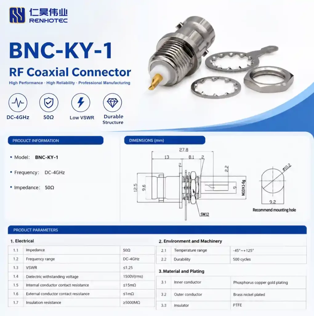
In short: this is the connector used to securely mount a BNC interface onto metal panels—whether on equipment chassis, instrument faceplates, or shielded enclosures.
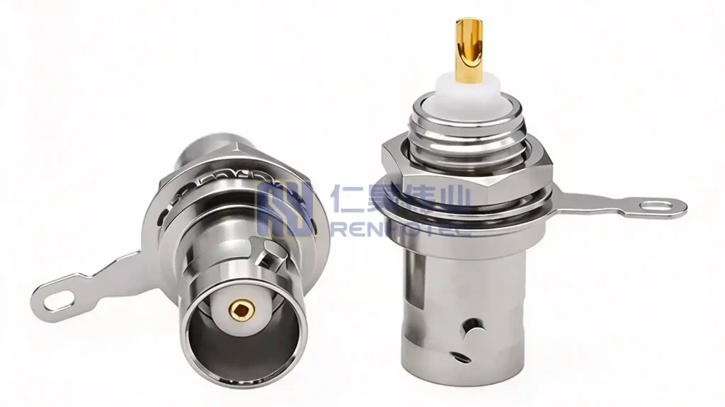
Free samples and CAD drawings are available upon request at the end of this article.

The panel interface serves as the primary gateway for signal input and output. With frequent mating cycles, the flaws of floating-mount designs often become apparent: loose connectors, stiff mating action, deformation of the inner conductor due to stress, and a gradual degradation of the Standing Wave Ratio (SWR).
Consequently, panel-mount connectors require more than just simple installation. Renhotec has designed the BNC-KY-1 as a panel-level solution featuring a dual-locking mechanism: a mounting flange combined with a threaded body.
01
Product Overview
Interface End
BNC female jack (socket contact) with a standard dual-pin bayonet quick-lock mechanism—simply insert and give it a gentle twist to lock; ready for immediate use with test cables.
Mounting End
Flange mounting holes paired with an M10×1.6g threaded lock; features an SW12 wrench flat in the middle, allowing for easy installation and removal using a standard open-end wrench.
Rear End
Solder-lug termination structure; supports reliable soldered connections to PCBs or internal wiring.
Core Alignment Challenge
The biggest challenge in panel mounting isn’t tightening the fastener—it’s alignment accuracy. Even a slight misalignment between the flange face and the chassis axis can cause stiff mating, lead to inner conductor deformation under stress, and result in increased signal reflection.
This model undergoes factory-level quality control for the coaxial alignment between the flange mating surface and the housing, ensuring precise centering with the mating plug once the panel is installed.
Summary: The stability of the panel mounting depends not on how tightly the connector is screwed in, but on the coaxial alignment.

Δ
Overview of BNC connector configurations: cable-end vs. panel-mount types (the bottom row shows panel/bulkhead-mount versions).
02
Electrical Specifications
Parameters are listed item-by-item based on industrial-grade testing standards:
| Parameter | Technical Specification |
|---|---|
| Impedance | 50Ω (Precise impedance matching, reduced signal reflection) |
| Operating Frequency | DC ~ 4GHz |
| VSWR | ≤ 1.25 (Full-band return loss control) |
| Dielectric Withstanding Voltage | 1500 V rms @ Sea level |
| Inner Conductor Resistance | ≤ 1.5 mΩ |
| Outer Conductor Resistance | ≤ 1 mΩ |
| Insulation Resistance | ≥ 5000 MΩ |
DC to 4 GHz —covering the mainstream frequency bands used in base station communications, broadcasting, and test & measurement. This frequency range is sufficient for panel-based signal input and output applications.
03
Materials, Mechanics, and Environment
The division of roles is clear: the gold-plated inner conductor tube offers elasticity and wear resistance; the nickel-plated outer shell provides corrosion resistance; and the PTFE component ensures stable high-frequency dielectric performance. Designed for a wide temperature range of -45°C to +125°C, it is suitable for both outdoor cabinets and industrial environments.
| Item | Specification |
|---|---|
| Interface Type | BNC Female (socket contact), dual-pin bayonet quick-lock mechanism |
| Mounting Method | Flange panel mounting + M10×1.6g thread, SW12 wrench flat |
| Rear Termination | Solder-lug termination |
| Inner Conductor | Phosphor bronze, Gold-plated (High elasticity, wear resistance) |
| Outer Conductor | Brass, Nickel-plated (Corrosion resistance, oxidation resistance) |
| Insulation Dielectric | PTFE (Polytetrafluoroethylene) |
| Mechanical Durability | ≥ 500 mating cycles |
| Operating Temperature | -45°C ~ +125°C |
| Environmental Compliance | 100% RoHS / REACH compliant |
04
Four Typical Applications
Communication Equipment Panels
RF input/output ports for base station equipment, repeaters, and indoor distribution system (DAS) main units.
Instrumentation Front Panels
Test ports on the panels of oscilloscopes, spectrum analyzers, and signal generators; built to withstand frequent mating cycles.
EMC Shielding Boxes & Test Fixtures
Signal feed-through adapters mounted on the housing, balancing shielding effectiveness with signal integrity.
Broadcasting & Power Utility Communication
Chassis-mounted interfaces for transmission equipment and power line carrier communication terminals, ensuring stable long-term operation.
05
Who It’s For—and Scenarios to Avoid
When to Choose This Model
Check these three criteria first: 50Ω system impedance, frequency within 4GHz, and a panel that allows for a mounting hole with rear-side soldering access—if these match, choose this model.
Scenarios to Avoid & Alternative Options
- 75Ω Video Surveillance Systems: Choose the 75Ω version instead. Mixing 50Ω and 75Ω causes impedance mismatch and increases the standing wave ratio (VSWR).
- High-Frequency Signals Above 4GHz: SMA, N-type, or 2.92mm series connectors are more suitable for higher frequency requirements.
- Field Sites Without Soldering Access: Consider the solder-free BNC-KY-2 model, which features a screw-clamp terminal for quick wiring using just a screwdriver.
06
A Word on Quality Control
Precision Alignment & Dielectric Control
BNC flange-mount models demand extremely high precision regarding coaxial alignment and the insulating dielectric. Any deviation in perpendicularity between the flange and housing, or positional offset of the PTFE insulator, directly impacts mating force and standing wave performance (VSWR).
Integrated CNC & Advanced Manufacturing
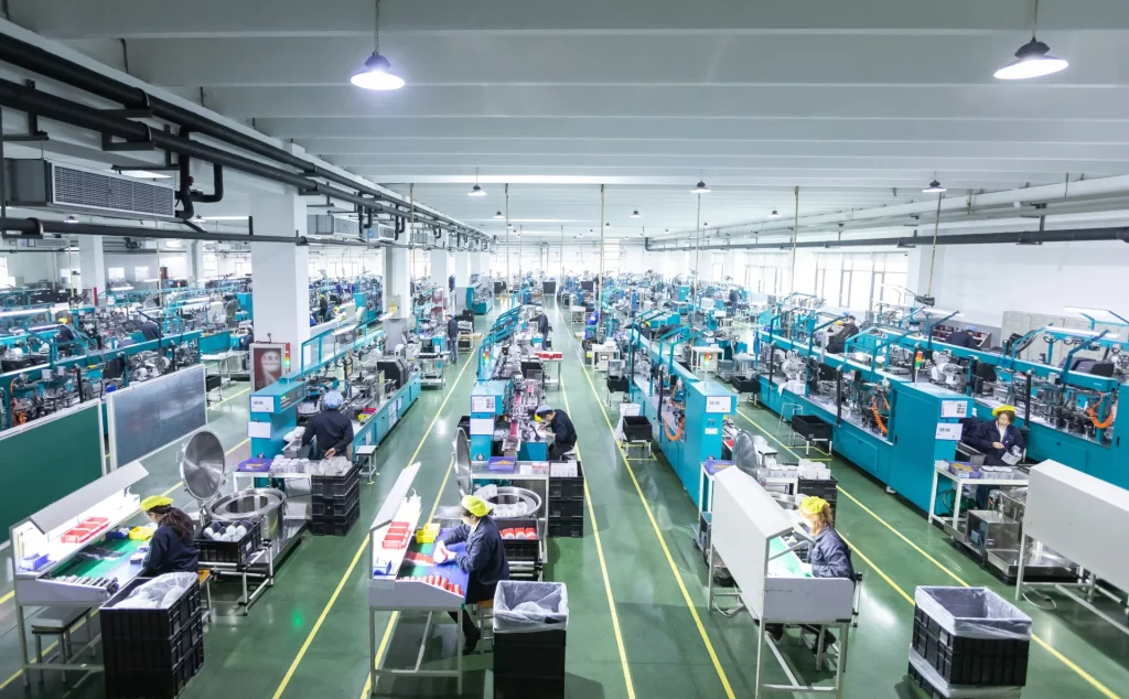
Leveraging a precision manufacturing facility spanning over 20,000 m² with over 18 years of RF connector expertise, Renhotec employs integrated high-precision CNC turning across the entire line. We strictly control coaxiality between the flange mounting surface and housing central axis, using precision molding for PTFE dielectric positioning.
20,000+ m² Facility
18+ years RF manufacturing expertise
ISO 9001 Certified
Strict quality system compliance
High-Purity Raw Stock
Phosphor bronze & brass materials
Our Quality Commitment: While any manufacturer can print a datasheet, it is our rigorous, item-by-item pre-shipment coaxiality and electrical testing that truly sets us apart.
Ready to Integrate or Customize Your BNC Solution?
Whether you need complete CAD files for panel cutout design, full technical datasheets, or custom RF coaxial cable assembly services, our engineering team is here to support your production.

Connectors & cable assemblies manufacturer.
Sharing insights on connectors and real-world applications.
Contact for datasheets, samples, or inquiries.
