
Selecting the right rf attenuators is critical to protecting sensitive equipment, shaping signal amplitudes, and ensuring signal integrity across your RF transmission lines. Whether you are running lab-scale validation or deploying automated production lines, this guide breaks down everything you need to know about attenuator design, key parameters, and selection strategies.
What Is an RF Attenuator?
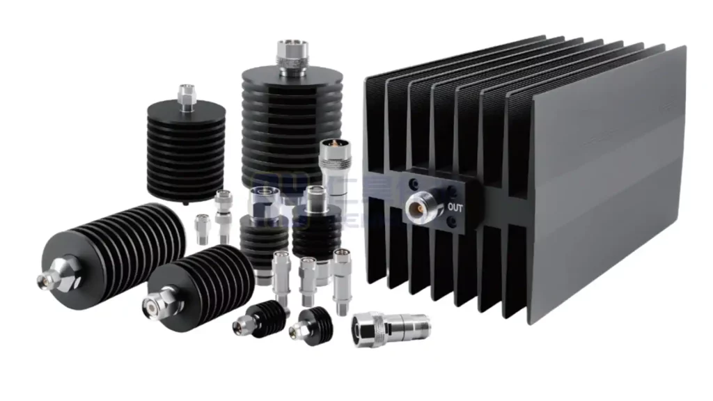
An RF attenuator is a passive two-port coaxial or microstrip component designed to reduce the power level of a radio frequency signal without distorting its wave shape. Unlike active components such as amplifiers, attenuators do not generate or increase signal power; instead, they dissipate part of the RF energy as heat.
Basic Definition & Core Function
- Signal Level Control: Reduces high RF power to optimal operating levels for downstream components.
- Instrument Protection: Shields sensitive analyzers, spectrum receivers, and detectors from power overloads.
- Impedance Matching: Improves voltage standing wave ratio (VSWR) by reducing reflections between mismatched RF stages.
Working Principle
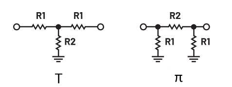
Inside a passive attenuator, signal reduction is achieved through resistive networks configured in standard topologies such as the π, T configurations. These networks absorb a portion of the incoming electromagnetic energy and dissipate it safely as thermal energy, keeping characteristic impedance (Z0, typically 50Ω or 75Ω) constant across both ports.
Types of RF Attenuators
RF attenuators can be classified by how their attenuation is adjusted and controlled. Some categories may overlap; for example, a step attenuator can be manually operated or digitally programmable.
By Attenuation Control
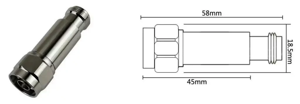
- Fixed Attenuators: Deliver a single, unchangeable attenuation value (e.g., a 3dB attenuator or 10dB pad). They offer high accuracy, compact size, and high power tolerance at a budget-friendly price point.
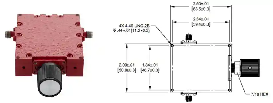
- Variable / Adjustable Attenuators: Encompass any device capable of changing attenuation values. In many product catalogs, the term refers specifically to continuously variable attenuators, where the attenuation can be adjusted without predefined steps, allow smooth, analog adjustment across a defined range using mechanical dials or voltage controls.
- Step Attenuators: Allow users to adjust signal reduction in discrete increments (e.g., 1dB steps from 0 to 110dB) via manual push-buttons or rotary switches—ideal for benchtop RF and microwave signal tuning.
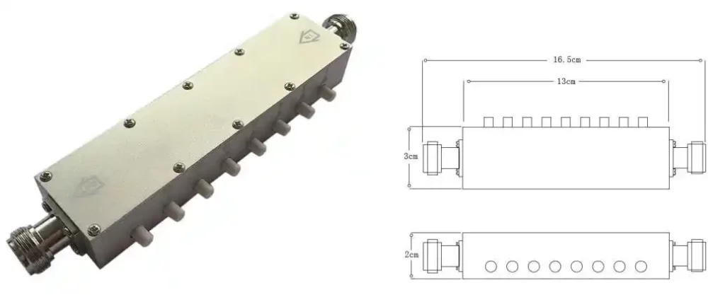
- Programmable RF Attenuator: Controlled via electronic interfaces (USB, SPI, LAN, or TTL). A Programmable RF Attenuator delivers fast switching speeds, high repeatability, and seamless integration into automated test environments.
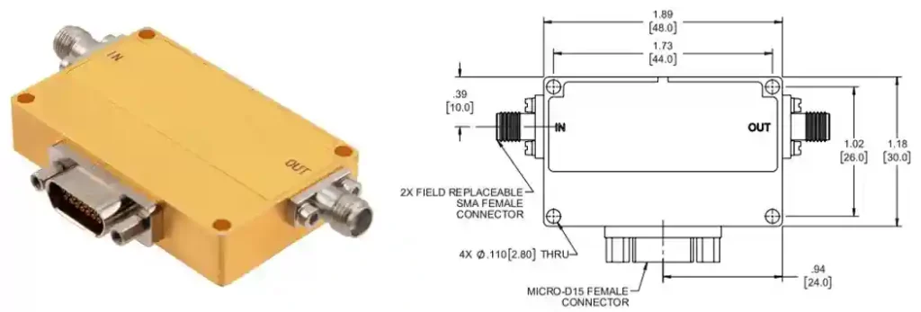
Programmable attenuators can use either variable or step-based attenuation architectures, with the primary distinction being electronic control and automation.
Explore Related Products
By Power Handling
- Low Power: Typically used in receiver chains, instrumentation, and board-level RF circuits.
- Medium Power: Commonly used in test systems and RF equipment where moderate continuous power handling is required.
- High Power: Designed for applications requiring substantial heat dissipation, such as power amplifier testing and transmitter development.
High-Power Consideration (Thermal Management):
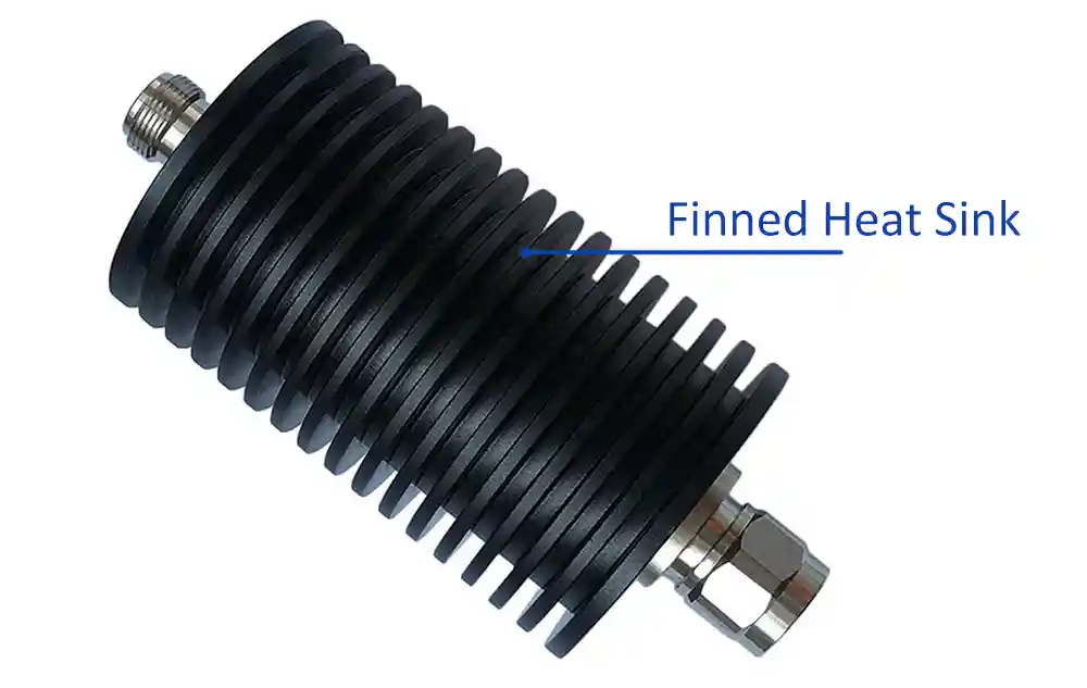
For low-to-medium power (<25W), passive convection cooling via integrated heat-sink fins is standard. However, for high-power RF applications (≥100W+), selecting the correct cooling method (e.g., Convection-Cooled vs. Liquid/Oil-Cooled) is critical to prevent thermal overload, attenuation drift, and catastrophic component failure during continuous-duty operation.
Key Specifications
When evaluating rf attenuators, pay close attention to these parameters:
| Parameter | Technical Significance | Typical Specification / Range |
|---|---|---|
| Attenuation (dB) | Exact ratio of signal power reduction: 10 log10(Pin / Pout). | 1 dB – 90 dB (e.g., 3, 6, 10, 20, 30 dB) |
| Frequency Range | Operating band. Exceeding this band compromises flatness and VSWR. | DC – 8 GHz (Up to 18 GHz / 40 GHz) |
| Power Rating (W) | Maximum continuous-wave (CW) power the attenuator can dissipate under specified conditions; peak-power capability depends on pulse duration, duty cycle, and design. | 2W, 5W, 10W, 15W, 25W, 30W, 50W, 100W, 150W, 200W, 300W, 500W |
| Impedance (Ω) | Characteristic system impedance to avoid power reflection. | 50 Ω (Standard) / 75 Ω (CATV) |
| VSWR | Voltage Standing Wave Ratio. Lower values mean lower internal signal reflection. | ≤ 1.2:1 |
| Attenuation Accuracy (dB) | Acceptable tolerance across operating frequency and temperature range. | ±0.3 dB – ±0.8 dB |
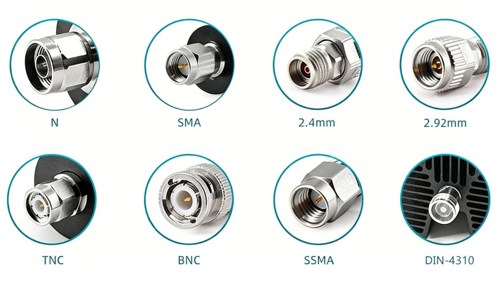
| Connector Type & Gender | Physical interface matching system cables and ports. | SMA, N-type, BNC, 7/16 DIN (Male / Female) |
| Operating Temperature | Environmental temperature limit without thermal degradation. | -55°C to +125°C |
| Cooling Method | Determines thermal dissipation behavior and continuous duty cycle capability. | Convection-Cooled (Heat Sink) / Oil-Cooled / Forced Air |
Applications & Industry Sectors
- Test & Measurement: Protects spectrum analyzers, vector network analyzers (VNAs), and power meters during transmitter testing.
- Telecommunications: Manages signal strength in cellular base stations, small cells, and 5G/6G infrastructure.
- Radar Systems: Controls power in T/R modules and protects receiver front-ends in pulse radar systems.
- Satellite Communications (SatCom): Regulates signal levels in ground station uplinks and satellite transponders.
- Aerospace & Avionics: Delivers ruggedized RF and microwave attenuator solutions for avionics, airborne communication, and high-frequency signal systems.
- Laboratory Research: Provides accurate signal attenuation for RF device characterization and prototype validation.
- Automotive & ADAS: Supports high-speed GMSL/FPD-Link SerDes testing, Mini-FAKRA cable validation, and 77GHz automotive radar testing.
How to Choose the Right RF Attenuator
Quick Selection Rule: Select an adjustable attenuator rf device if your test levels vary frequently; use a fixed passive attenuator when working with fixed power thresholds and tight budgets. A margin of 20–30% is often used as a practical starting point, but the manufacturer’s derating curve should take precedence.
Buyer’s Avoid-Mistakes Checklist
- Gender Mismatch: Double-check whether your setup requires Plug-to-Jack (Male-Female), Male-Male, or Female-Female configurations before ordering.
- Peak Power vs. CW Power Confusion: Do not confuse Continuous Wave (CW) power ratings with Peak Pulse power limits. High peak pulses can cause dielectric breakdown even if average power is within spec.
- Heat Dissipation Space: High-power attenuators need adequate airflow. Installing a 100W finned attenuator in a sealed enclosure without heat sinking will lead to thermal failure.
- Connector Torque Limits: Over-tightening precision connectors (such as 3.5mm or 2.92mm) can permanently deform port mating planes, degrading VSWR performance.
RF Attenuator vs. Other RF Components
Attenuator vs. Amplifier
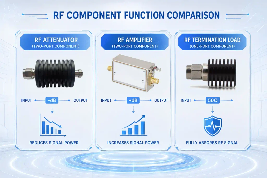
An attenuator reduces signal power while preserving wave shape; an amplifier increases power using active semiconductor circuitry.
Attenuator vs. Dummy Load / Termination
An attenuator is a two-port device that passes reduced power to an output port. A dummy load (termination) is a one-port device designed to absorb 100% of incoming RF power without passing it along.
Attenuator vs. Standard Resistor
A standard resistor lacks controlled characteristic impedance and exhibits high parasitic capacitance and inductance at high frequencies. An RF attenuator uses microwave-grade resistive thin/thick films designed to maintain flat 50 Ohm impedance across gigahertz bands.
Customization Options
When off-the-shelf components do not match your exact test requirements, tailored manufacturing options include:
- Frequency Tuning: Extended band performance (e.g., custom DC to 50 GHz solutions).
- Specific Attenuation Values: Non-standard values such as 1.5 dB, 7 dB, or 23 dB.
- High-Power Thermal Housings: Custom fin geometry, liquid-cooling blocks, or forced-air brackets.
- Mixed Connector Interfaces: Hybrid combinations like SMA Male to N-Type Female to eliminate extra adapters.
- Impedance Matching: Custom 50 Ω to 75Ω impedance matching pads.
- Special Enclosures: Non-magnetic, waterproof (IP67/IP68), or space-qualified coatings.
Why Choose Renhotec for RF Attenuators?
At Renhotec, we design and manufacture high-performance RF attenuators, RF coaxial connectors, and cable assemblies for demanding industrial, telecommunications, aerospace, and test & measurement applications.
- Broad Product Range: From compact 3dB attenuator pads to high-power finned units and variable attenuators, we cover DC to 110 GHz applications.
- Precision Manufacturing: Stringent quality control ensures low VSWR, flat frequency response, and reliable power handling.
- OEM/ODM Customization: Custom connector pairings, specialized power housings, and tailored attenuation values built to your specifications.
- Direct-from-Factory Value: Fast lead times, competitive pricing, and full RoHS/REACH compliance support your supply chain needs.

FAQ
Q1: Why are 3-resistor π or T attenuators preferred over 2-resistor L-pad attenuators in RF circuits?
L-pad attenuators lack enough independent variables to achieve a bidirectional 50 Ω impedance match while providing arbitrary attenuation. While an L-pad may work for negligible attenuation (1-2 dB), higher attenuation levels cause severe impedance mismatch, leading to poor return loss and signal reflections. Using three resistors (π or T topology) provides the necessary degrees of freedom to control attenuation while keeping both ports matched to 50 Ω.
Q2: Why add attenuation after amplification instead of before the first stage?
Placing attenuation before the first stage severely degrades the system’s overall Noise Figure (NF), as early noise cannot be filtered out later (Friis’ formula). Amplifying first boosts the signal above the noise floor, ensuring that interstage loss or attenuator noise has a much smaller impact on the system’s Signal-to-Noise Ratio (SNR).
Q3: Are there specific scenarios where a T attenuator topology is advantageous?
T attenuator topologies can be advantageous when a symmetrical resistive network is preferred, particularly for lower attenuation levels and lower-frequency applications where parasitic effects are less significant. Their straightforward structure can simplify impedance matching and circuit implementation while providing a predictable attenuation level. For higher frequencies or more demanding RF applications, however, the choice between T and π topologies should also consider bandwidth, parasitic effects, power handling, and PCB layout.
Q4: What is the difference between 50 Ω and 75 Ω RF attenuators?
It is not recommended. Connecting a 50 Ohm attenuator to a 75 Ohm system causes an impedance mismatch, increasing signal reflections, elevating VSWR, and causing ghosting or data loss in video/broadband channels.
Q5: What happens if an RF attenuator exceeds its rated power?
Exceeding the power rating generates excessive heat inside the resistive element. This causes value drift, permanent resistance changes, or catastrophic thermal burnout—potentially exposing downstream test instruments to dangerous power levels.
Q6: What is the difference between CW and peak power ratings?
CW (Continuous Wave) power rating refers to the maximum average power an attenuator can handle continuously. Peak power handling refers to the maximum instantaneous pulse power the device can tolerate without dielectric breakdown, provided the average power remains below the CW threshold.
Looking for the Right RF Attenuator?
From fixed and step attenuators to variable and programmable solutions, Renhotec provides RF attenuation solutions tailored to your frequency, power, impedance, and connector requirements.
Need a custom RF attenuator? Share your specifications with our team.
Get a Quote
Connectors & cable assemblies manufacturer.
Sharing insights on connectors and real-world applications.
Contact for datasheets, samples, or inquiries.
