
What Is an MMCX Connector?
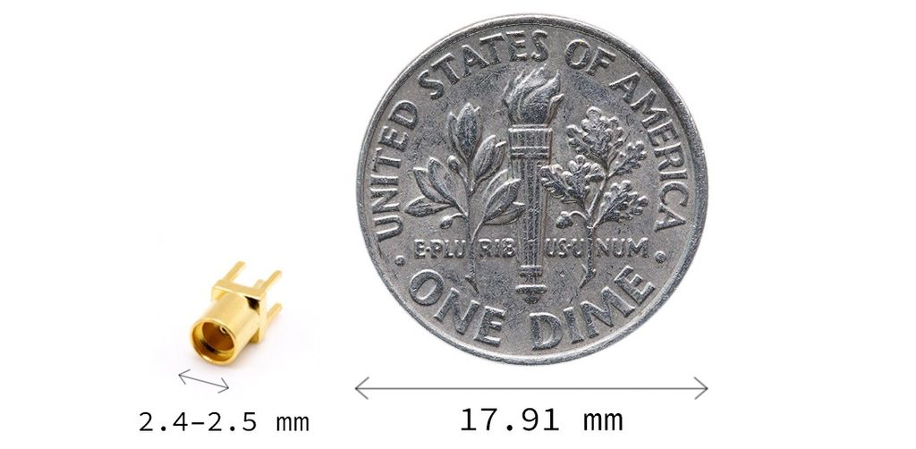
The Micro-Miniature Coaxial (MMCX) connector is a micro-miniature RF connector interface developed in the 1990s as a smaller alternative to the MCX (Micro Coaxial) standard. Designed for applications where board space and weight savings are critical, MMCX connectors deliver reliable high-frequency performance up to 6 GHz. Their snap-on mating mechanism enables quick connection and 360-degree rotation, making them ideal for modern compact wireless devices.
Key Features of MMCX Connectors
- Compact dimensions for space-constrained equipment
- Snap-on mating without a threaded coupling nut
- 50-ohm characteristic impedance
- Broadband performance commonly extending to 6 GHz
- Straight and right-angle configurations
- Cable-mount and PCB-mount options
- Rotational freedom after mating
- Compatibility with miniature coaxial cables
These features make MMCX suitable for dense RF assemblies where a traditional threaded connector may occupy too much space.
MMCX Connector Design and Construction
An MMCX connector maintains the basic coaxial structure of center conductor, dielectric, and outer conductor while reducing the overall interface size. Its mechanical interface is specifically designed for quick push-on mating.
Center Contact
A well-controlled center contact is important for maintaining low contact resistance and stable RF performance. Depending on the connector design, manufacturers commonly use brass or beryllium copper with a conductive plating such as gold.
Dielectric
Polytetrafluoroethylene (PTFE) is commonly used in MMCX connectors because of its electrical properties and temperature stability. However, dielectric materials can vary by product family.
Outer Conductor
The outer conductor provides the RF return path and shielding around the center contact. Its geometry directly influences impedance control, shielding effectiveness, and RF loss. The outer conductor also forms part of the mechanical mating interface.
Snap-On Mating Interface
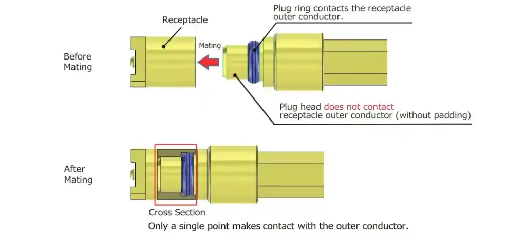
Unlike threaded interfaces (such as SMA) that require precise torque specifications, the MMCX uses a spring-loaded retention clip integrated into the outer shell. This snap-on mechanism yields a tactile click when fully seated, securing the connection against vibration without requiring lock washers or wrenches.
360° Rotation
Because the snap-ring permits uninhibited axial rotation, the connected coaxial cable can swivel freely. This design mitigates torsional stress on solder joints, protecting PCB trace pads during device handling or assembly.
Types of MMCX Connectors
MMCX connectors are available in several mechanical configurations. Selection normally depends on the mating interface, installation method, PCB layout, cable routing, and available space.
MMCX Male vs Female
An MMCX plug normally contains the male center pin, while an MMCX jack contains the female socket. When specifying a connector, confirm both the electrical interface and the mechanical gender rather than relying only on “male” or “female” terminology.
Straight vs Right-Angle MMCX
Right-angle designs can reduce cable bending space, while straight connectors may simplify routing in certain assemblies.
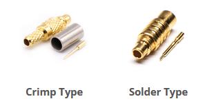
Common versions include crimp, solder, and other cable termination structures depending on cable type.
For example, MMCX cable connectors are available for miniature cables such as RG178 and RG196.
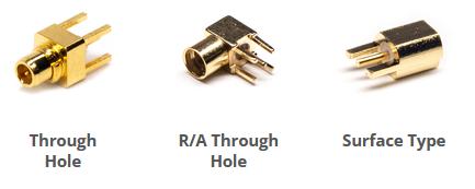
They may use through-hole, surface-mount, or other board attachment methods. Straight and right-angle configurations allow designers to adapt the connector to different board layouts.
Find the Right MMCX Connector
Use our website filters to easily find the MMCX connector that fits your needs.
View MMCX ConnectorMMCX Connector Specifications
MMCX performance depends on the exact connector design, cable, termination, and test configuration. The following values illustrate common specifications rather than universal limits.
| Specification | Typical Example |
|---|---|
| Impedance | 50 Ω |
| Frequency range | DC–6 GHz |
| VSWR | ≤1.25 to 4 GHz; ≤1.40 from 4–6 GHz |
| Insertion loss | ≤0.1√f(GHz) dB in some designs |
| Center contact resistance | ≤10 mΩ |
| Outer contact resistance | ≤5 mΩ |
| Operating temperature | Often around –40°C to +90°C; other designs differ |
| Mating durability | 500 cycles minimum in many product families |
*Actual specifications vary by manufacturer and connector configuration.
Where Are MMCX Connectors Used?
MMCX connectors are used when compact dimensions and convenient RF connections are required.

- Wireless Communications
MMCX interfaces can be found in wireless communication modules, Bluetooth equipment, Wi-Fi devices, and antenna interfaces.
- GPS & GNSS
GPS and GNSS equipment often requires compact antenna connections. MMCX connectors are used in receivers, navigation equipment, tracking systems, and related RF modules.
- Wi-Fi & Networking
Compact wireless networking equipment may use MMCX or related miniature coaxial interfaces to connect antennas and RF modules.
- RF Modules
MMCX connectors can provide a detachable RF interface between a module, PCB, antenna, or test cable.
- Medical Equipment
MMCX is also used in compact medical electronics. Specialized non-magnetic MMCX versions are available for applications where magnetic materials may be undesirable, including certain MRI-related environments.
- Other Compact RF Applications
IoT equipment
Portable RF devices
Industrial automation
Telematics
Drones and unmanned systems
RF development boards
Test and measurement equipment
In-ear monitor and audio-related RF connections
MMCX vs Other RF Connectors
MMCX is not simply a smaller version of every other RF connector. Its mechanical interface, dimensions, frequency capability, and application priorities differ from MCX, SMA, U.FL/IPEX, and SMP.
| Connector | Typical Coupling | Typical Frequency | Main Design Consideration |
|---|---|---|---|
| MMCX | Snap-on | DC–6 GHz | Compact, rotational, quick connection |
| MCX | Snap-on | DC–6 GHz typical | Larger than MMCX, compact RF interface |
| SMA | Threaded | Up to many GHz | Robust threaded connection |
| U.FL/IPEX | Snap-on | Up to 18 GHz depending on series | Extremely low profile |
| SMP | Snap-on | Up to 40 GHz | High-frequency compact interconnect |
MMCX vs MCX
MCX and MMCX both use snap-on coupling and are commonly available in 50-ohm versions. MMCX is physically smaller, with a typical diameter of around 2.4–2.5 mm.
Choose between them based on available space, mating interface, cable requirements, and required mechanical performance. They should not be assumed to be directly interchangeable.
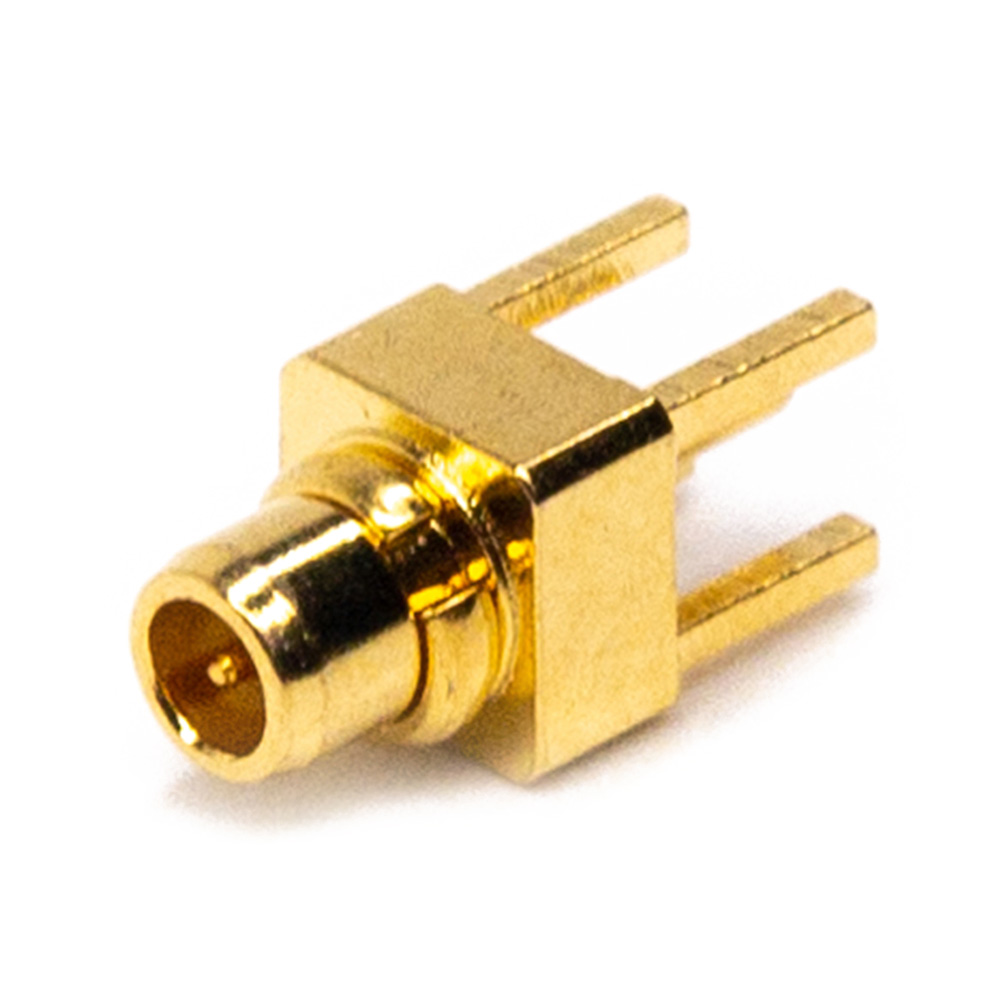
MMCX Male

MMCX Female

MCX Male
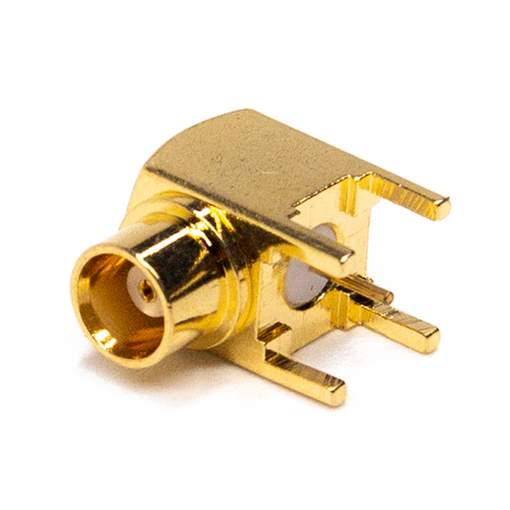
MCX Female

MMCX Connectors

MCX Connectors
MMCX vs SMA
SMA normally uses a threaded coupling mechanism, while MMCX uses snap-on coupling. SMA is therefore often selected where a threaded mechanical connection is preferred, while MMCX can be advantageous where compact size and rapid connection are more important.
An adapter such as an MMCX to SMA adapter can bridge the two interfaces when the electrical and mechanical requirements are compatible.
MMCX vs U.FL / IPEX
U.FL is generally designed for extremely compact PCB applications, with mated heights typically around 1.9–2.4 mm and frequency ratings reaching up to 18 GHz, depending on the specific series.
MMCX is physically larger but generally offers a more accessible snap-on interface for applications requiring repeated cable connection and disconnection.
MMCX vs SMP
SMP connectors support higher frequencies (up to 40 GHz) and blind-mate configurations, making them common in advanced military radar and satellite sub-systems. MMCX offers a more cost-effective solution for standard commercial electronics operating below 6 GHz.
How to Choose the Right MMCX Connector
Choosing an MMCX connector should start with electrical requirements and then move to mechanical and cable considerations.
Step 1: Determine Impedance
For standard MMCX RF applications, verify that the connector, cable, PCB transmission line, and equipment all use the required impedance, typically 50 Ω.
Step 2: Check Frequency
Confirm the maximum operating frequency of the complete RF path rather than only the connector. Cable type, PCB transition, and assembly quality can affect high-frequency performance.
Step 3: Select Gender
Determine whether the application requires an MMCX plug or jack. Also verify the mating interface on the equipment or PCB.
Step 4: Select Mounting Type
Choose between cable-mount and PCB-mount versions. PCB connectors can be straight or right-angle and may use through-hole or SMT mounting.
Step 5: Consider Mechanical Requirements
- Available installation space
- Cable routing direction
- Required mating cycles
- Engagement and disengagement force
- Rotation requirements
- Vibration and shock conditions
- Environmental temperature
Step 6: Select the Right Coaxial Cable
The connector and cable must be compatible in terms of cable diameter, dielectric construction, center conductor, shielding, and termination method. For miniature cable assemblies, cables such as RG178, RG196, or micro-coaxial cables may be available depending on the connector design.
MMCX Cable Assemblies
An MMCX cable assembly combines an MMCX connector with a selected coaxial cable and termination method. The complete assembly should be evaluated as one RF transmission path.
Common MMCX Cable Configurations

MMCX Cable Assembly with RG178 Coaxial Cable. This series of cables has a maximum frequency of 3GHz, a propagation speed (VoP) of 70%, a FEP sheath, and a heat shrinkable tail.

Low Loss SMA to MMCX Cable Assemblies Using LMR100 Series Coaxial Cable. This cable series supports frequencies up to 6 GHz, equivalent to LMR-100, with shielding efficiency exceeding 90 dB. It boasts a 66% phase velocity, minimal insertion loss, and features double-shielded PVC insulation.
Choosing the Right Coaxial Cable
- Operating frequency
- Cable attenuation
- Outer diameter
- Flexibility
- Shielding
- Temperature rating
- Minimum bend radius
- Connector compatibility
The cable can influence the final VSWR, insertion loss, and mechanical reliability of the assembly.
Custom MMCX Cable Assemblies
Custom MMCX cable assemblies can be specified according to connector combination, cable type, length, orientation, shielding, termination, and electrical test requirements.
For B2B applications, it is useful to provide the required mating connector, operating frequency, impedance, cable length, environmental conditions, and target RF performance when requesting a quotation.
Custom MMCX Cable Assemblies
Build your own MMCX cable assembly with custom lengths, connector types, and cable materials to fit your exact application.
Start CustomizationHow to Mate and Disconnect an MMCX Connector
MMCX connectors use a push-on interface, so installation is generally faster than threaded RF connectors.
Mating Procedure
- Align the male pin visually and coaxially with the female receptacle.
- Push the male plug straight into the female jack without twisting.
- Apply steady pressure until an audible click confirms the internal snap-ring has locked into the detent groove.
Disconnecting Procedure
- Grasp the knurled main body of the male connector.
- Pull straight back along the axis of the connector interface.
- Avoid yanking directly on the coaxial cable to prevent damaging crimp joints or tearing PCB pads.
Common Installation Mistakes
- Off-Axis Insertion: Mating at an angle can bend the fragile 0.5 mm center pin.
- Pulling the Cable Strain Relief: Exerts tensile force on internal solder joints, causing open circuits over time.
- Exceeding Mating Force: Excessive force indicates misalignment; continuing will damage the female contact leaves.
How Are MMCX Connectors Tested?
MMCX connectors can be evaluated through electrical, mechanical, dimensional, and environmental testing. IEC 61169-52 provides the relevant sectional specification and test framework for MMCX connectors.
VSWR
VSWR testing evaluates impedance matching across the specified frequency range. A vector network analyzer (VNA) is commonly used to measure S-parameters and derive VSWR or return loss.
Insertion Loss
Insertion loss testing measures how much RF power is lost through the connector or complete cable assembly.
For cable assemblies, the measurement should include both connectors and the cable rather than attributing the total loss to the connector alone.
Return Loss
Return loss is derived from the reflected signal and provides another way to evaluate impedance matching. A higher return loss generally corresponds to lower reflected power.
Mechanical and Electrical Inspection
- Dimensional inspection
- Center and outer contact resistance
- Insulation resistance
- Mating and disengagement force
- Mating-cycle durability
- Visual inspection
- Material and plating verification
- Environmental testing where required
The specific test sequence and acceptance criteria should follow the applicable product specification and customer requirements.
FAQs
Q: Can MMCX connect to SMA or MCX?
Yes, through a properly specified adapter or cable assembly. The adapter must match the connector gender, impedance, frequency range, and mechanical interface. For example, an MMCX-to-SMA cable assembly can connect equipment using the two different interfaces. For MCX equipment, an MCX to MMCX adapter or cable assembly may be used when the electrical and mechanical requirements are compatible.
Q: Is MMCX suitable for high-frequency applications?
MMCX is commonly used up to 6 GHz, making it suitable for many wireless, GNSS, IoT, and compact RF applications. For applications substantially above this range, connectors such as SMP may offer higher-frequency capability depending on the system requirements.
Q: What is the main difference between MMCX and U.FL connectors?
MMCX connectors are robust, snap-on components rated for 500 mating cycles and 360-degree rotation. U.FL connectors offer a much lower profile but are rated for only ~30 mating cycles and lack continuous rotation.
Looking for the Right MMCX Connector?
From individual connectors to custom MMCX cable assemblies, the right configuration depends on your RF performance, cable, mounting, and mechanical requirements.
Tell us your connector type, cable specification, frequency range, and assembly requirements, and we can help you identify a suitable MMCX solution.

As an industry specialist at Renhotec Group, I have years of expertise in the field of electronic interconnection. Founded in 2008, Renhotec Group is a global leader in designing and manufacturing connectors, cables, and custom electronic components for a wide range of industries. We are committed to providing high-performance interconnect solutions, leveraging technical innovation and rigorous quality standards to empower global customers across industrial, RF, and EV sectors.
