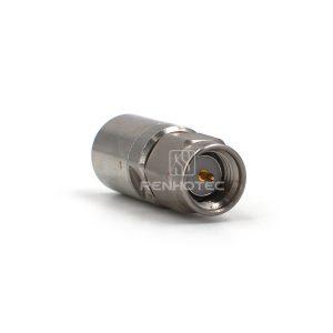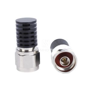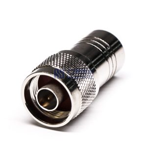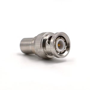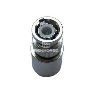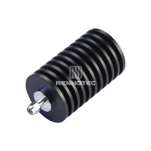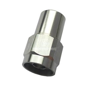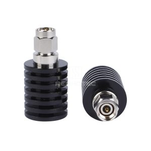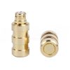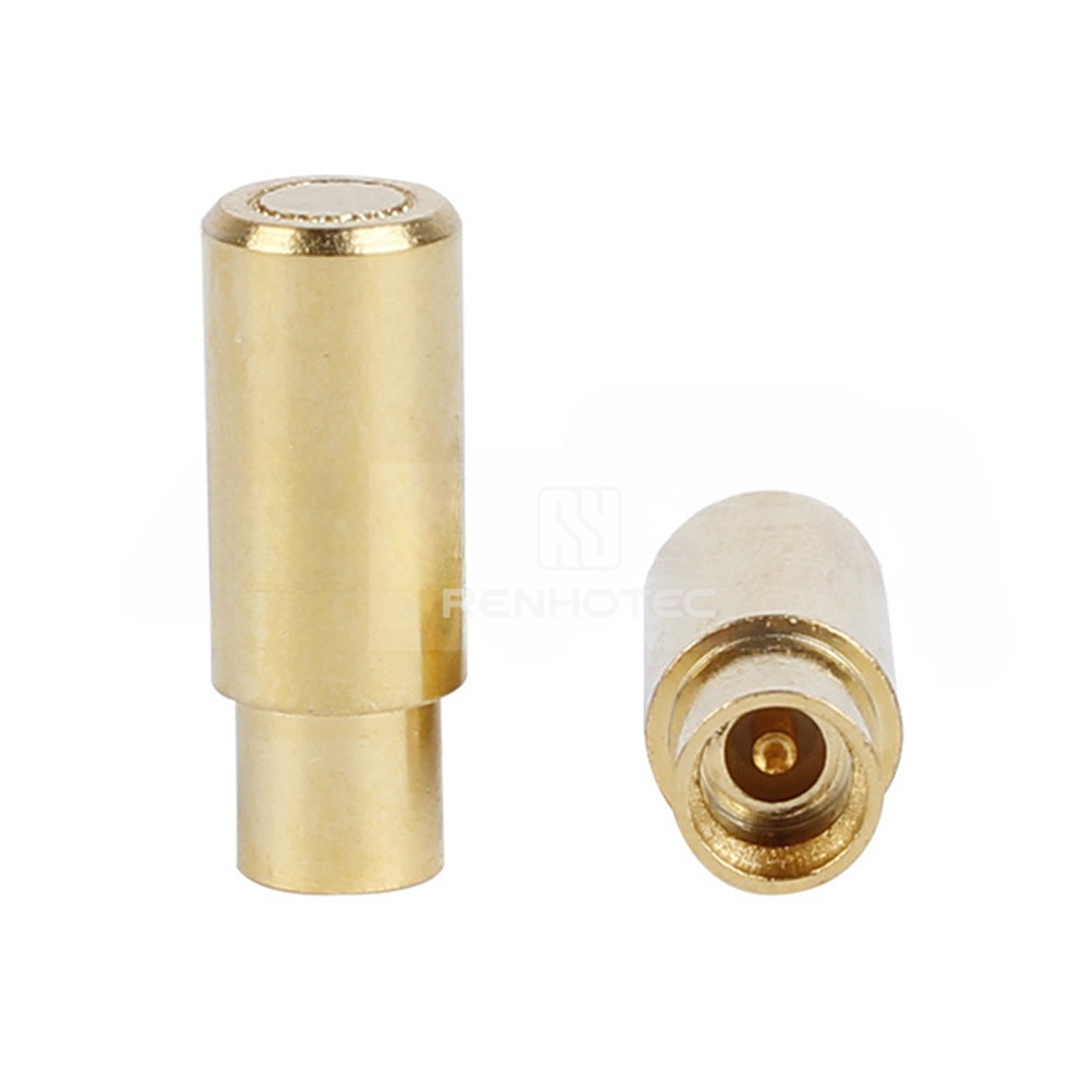
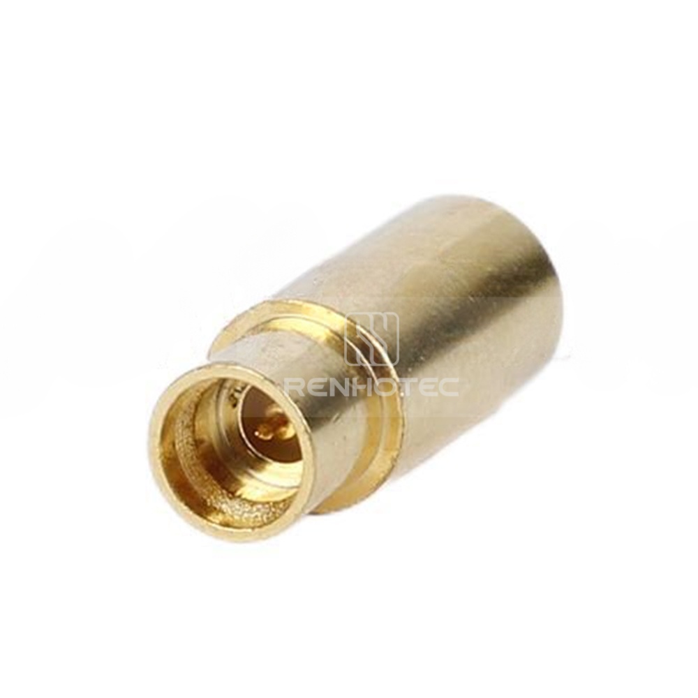
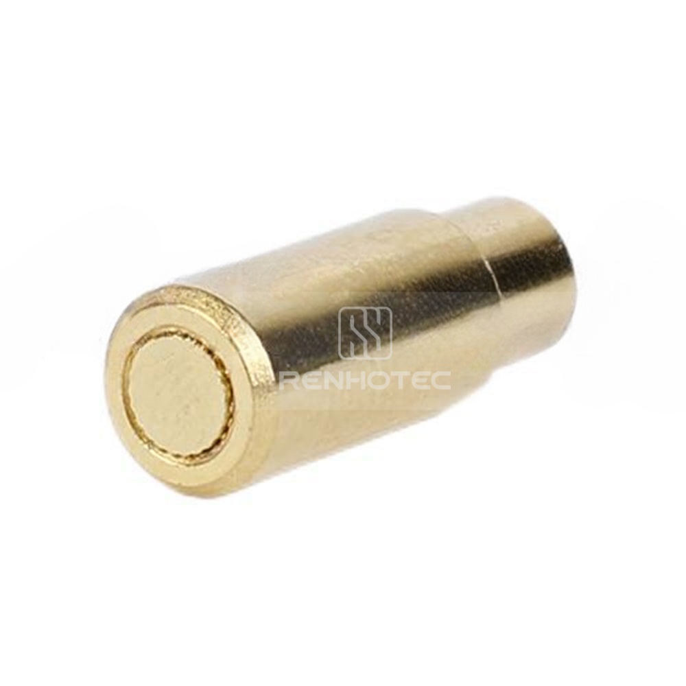
SMP-50J-2W SMP Male Connector 2W 26.5G VSWR 1.35 Ohms Terminal Load
SMP male 2W termination for 26.5 GHz operation. Used in miniaturized modules, phased-array calibration ports, and onboard test points. Blind-mate compatible design aids quick integration into dense multi-channel assemblies.
Product Specification
| Center Contact Resistance | ≤3mΩ |
||
|---|---|---|---|
| Outer Contact Resistance | ≤2mΩ |
||
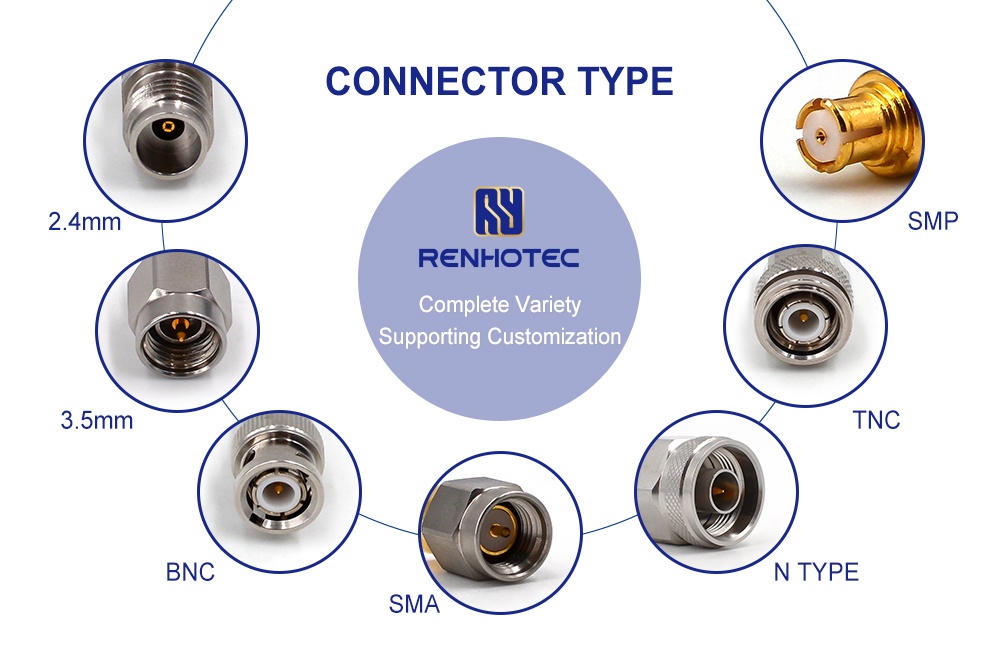
| Connector Type | SMP |
||
| IP Rating | IP67 |
||
| Impedance | 50Ω |
||
| Operating Temperature | -45°~+125° |
||
| Insulation Resistance | ≥5000Ω |
||
| Frequency Range | 0-6GHz VSWR:1.2MAX; 6-12GHz VSWR:1.25MAX; 12-18GHz VSWR:1.3MAX; 18-26.5GHz VSWR:1.35MAX |
||
| Center Contact Resistance | ≤3mΩ |
Outer Contact Resistance | ≤2mΩ |
| Connector Type | SMP |
IP Rating | IP67 |
| Impedance | 50Ω |
Operating Temperature | -45°~+125° |
| Insulation Resistance | ≥5000Ω |
Frequency Range | 0-6GHz VSWR:1.2MAX; 6-12GHz VSWR:1.25MAX; 12-18GHz VSWR:1.3MAX; 18-26.5GHz VSWR:1.35MAX |
| Coupling Nut Material | Brass |
||
|---|---|---|---|
| Durability | ≥500 Cycles |
||
| Inner Conductor Material | Brass, Gold Plated |
||
| Outer Conductor Material | Brass, Gold Plated |
||
| Insulation Material | PTFE |
||
| Power Handling | 2W |
||
| Withstanding Voltage | 1000VRMS |
||
| Coupling Nut Material | Brass |
Durability | ≥500 Cycles |
| Inner Conductor Material | Brass, Gold Plated |
Outer Conductor Material | Brass, Gold Plated |
| Insulation Material | PTFE |
Power Handling | 2W |
| Withstanding Voltage | 1000VRMS |
| Center Contact Resistance | ≤3mΩ |
|---|---|
| Outer Contact Resistance | ≤2mΩ |
| Connector Type | SMP |
| Coupling Nut Material | Brass |
| Durability | ≥500 Cycles |
| IP Rating | IP67 |
| Impedance | 50Ω |
| Inner Conductor Material | Brass, Gold Plated |
| Outer Conductor Material | Brass, Gold Plated |
| Insulation Material | PTFE |
| Operating Temperature | -45°~+125° |
| Insulation Resistance | ≥5000Ω |
| Power Handling | 2W |
| Withstanding Voltage | 1000VRMS |
| Frequency Range | 0-6GHz VSWR:1.2MAX; 6-12GHz VSWR:1.25MAX; 12-18GHz VSWR:1.3MAX; 18-26.5GHz VSWR:1.35MAX |
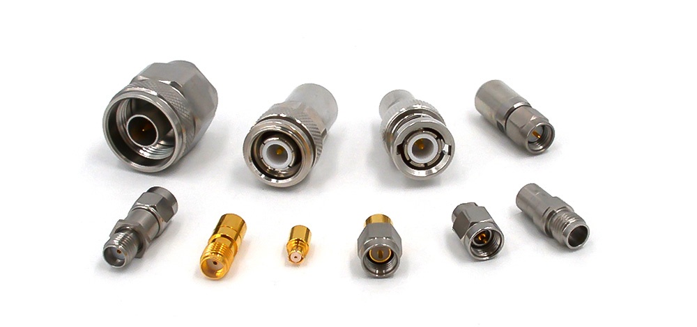
RF coaxial loads are basic components in the RF signal chain, typically placed at the end of the line and also known as RF terminators. Their main function is to fully absorb microwave energy from the transmission line, thereby improving circuit matching, preventing unwanted reflections, and minimizing interference. In addition, they can control power levels, serve as decoupling elements, act as reference standards, and help reduce interference in radar systems.
Product Features
- Core functions: Efficiently absorbs microwave energy, improves circuit matching, reduces reflections and interference, and ensures overall system stability.
- Versatile and adaptable: Controls power, isolates interference, supports calibration testing, reduces radar system interference, and adapts to multiple application scenarios.
- Reliable performance: Standard impedance compatibility, low VSWR for improved efficiency and signal quality, supports a wide range of power levels, frequencies, and temperatures, ensuring stable and dependable operation.
Application Scenarios
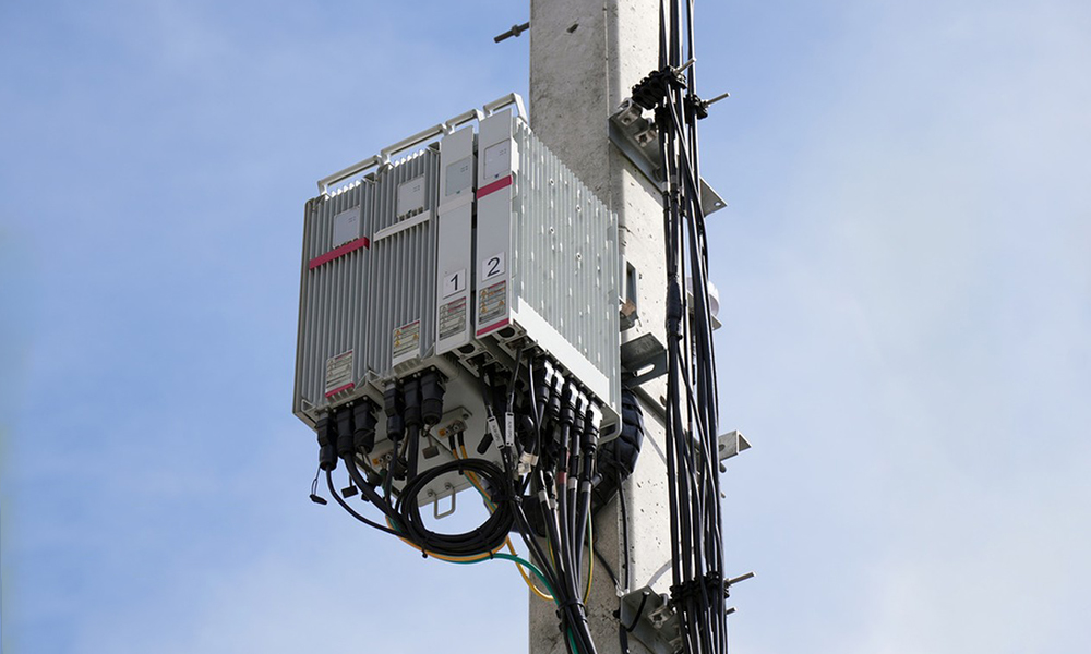
- Wireless communication: devices such as base stations, mobile phones, satellite communications, etc.
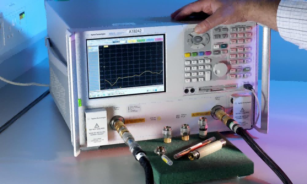
- Instrumentation: network analyzers, signal generators, etc.
- Aerospace: communication, navigation, and radar systems for aircraft.

RF Coaxial Loads FAQ
1. What factors should be considered when choosing a load?
The main ones are frequency range, power capacity, and impedance matching.
2. Can loads with different power ratings be used together?
No. They need to be used with transmission lines that have corresponding connectors.
3. What are the effects of impedance mismatch?
It can cause signal reflections, which may reduce efficiency or even damage the equipment.
4. What types of RF coaxial loads are there?
Common types include fixed and adjustable loads. They can also be categorized as low, medium, or high-power loads based on power rating.
5. How long is the service life of a load?
With normal use, service life typically ranges from a few years to over ten years, depending on the operating environment.
Microwave Components CatalogDownload