Zonal Architecture: Why Automotive Ethernet Wins
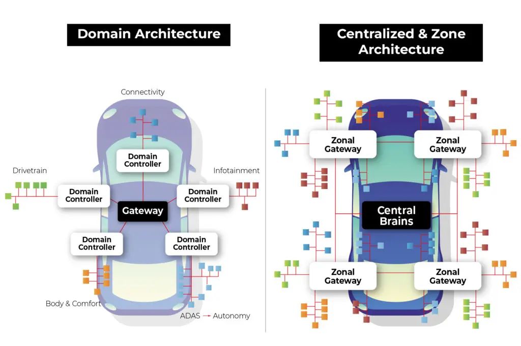
The automotive industry is undergoing a fundamental transformation in Electronic/Electrical (E/E) architecture. Traditional domain-based systems are hitting a “wiring wall”—where the proliferation of ADAS sensors and high-resolution displays makes point-to-point LVDS cabling physically unsustainable due to weight and complexity.
Zonal Architecture solves this by grouping components by physical location, utilizing a high-speed Ethernet backbone to link zonal gateways to a central computer. While LVDS remains efficient for unidirectional video, it lacks the bidirectional networking flexibility required for a scalable, software-defined backbone. The Automotive Ethernet vs. LVDS transition is no longer just about speed; it is about topology. 1000BASE-T1 (Single Pair Ethernet) provides the 1 Gbps full-duplex throughput necessary to consolidate multiple data streams over a single unshielded or shielded twisted pair, drastically reducing harness mass while ensuring deterministic communication.
Decoding OPEN Alliance TC9 and Technical Standards
OPEN Alliance TC9 defines physical-layer compliance requirements for 1000BASE-T1 links, including Return Loss (RL), Insertion Loss (IL), and Mode Conversion performance across the operating frequency range. Unlike conventional four-pair Ethernet, 1000BASE-T1 transmits Gigabit data over a single twisted pair, placing tighter SI and EMC requirements on connector geometry, cable symmetry, and shielding quality.
In practice, connector transitions and untwist length are common sources of impedance discontinuity in 1000BASE-T1 assemblies. Poor shield termination consistency can also increase mode conversion and radiated emissions during EMC validation. To verify physical-layer performance, VNA-based SI testing is commonly used to evaluate Return Loss, insertion loss, and mode conversion performance against OPEN Alliance and OEM requirements.
100BASE-T1 vs. 1000BASE-T1: Key Physical Layer Differences
| Feature | 100BASE-T1 | 1000BASE-T1 |
|---|---|---|
| Data Rate | 100 Mbps | 1 Gbps |
| Bandwidth | ~33 MHz | ~600 MHz |
| Encoding | PAM3 | PAM3 (8B/3B/2B mapping) |
| Symbol Rate | 66.7 MBaud | 750 MBaud |
| Cable Type | UTP / STP | STP (Recommended for EV) |
| Connector | FAKRA / HSD | Mini-FAKRA / MATE-AX |
Upgrading from 100BASE-T1 to 1000BASE-T1 alters more than data rates. It changes signal encoding and physical layer specifications. 100BASE-T1 transmits PAM3 signals at a 66.7 MBaud symbol rate. 1000BASE-T1 operates at a signaling rate of approximately 750 MBd using PAM3 encoding. This shift expands the required bandwidth to 600 MHz. For engineers, this means that while 100M Ethernet was relatively forgiving regarding cable twists and connector shielding, 1000BASE-T1 demands absolute precision in signal integrity. A link that passes 100M validation may fail SI validation at higher frequencies due to excessive Return Loss or Mode Conversion at higher frequencies.
Choosing between these two standards often depends on the specific domain within the EV zonal architecture. 100BASE-T1 remains the cost-effective “workhorse” for basic body control modules and simple telematics where data requirements are modest. However, for the backbone of a Zonal Controller or the high-resolution feed from an ADAS camera, 1000BASE-T1 is the widely adopted. As a cable assembly supplier, we emphasize that 1000BASE-T1 cable assemblies must use high-performance connectors like Mini-FAKRA or MATE-AX to maintain the necessary headroom, whereas legacy 100M links could often get by with standard unshielded connectors in less noisy environments.
Selecting Connectors: HSD, MATE-AX, and Mini-FAKRA
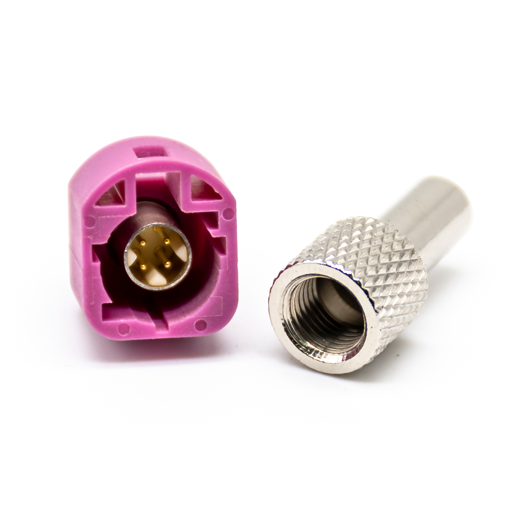
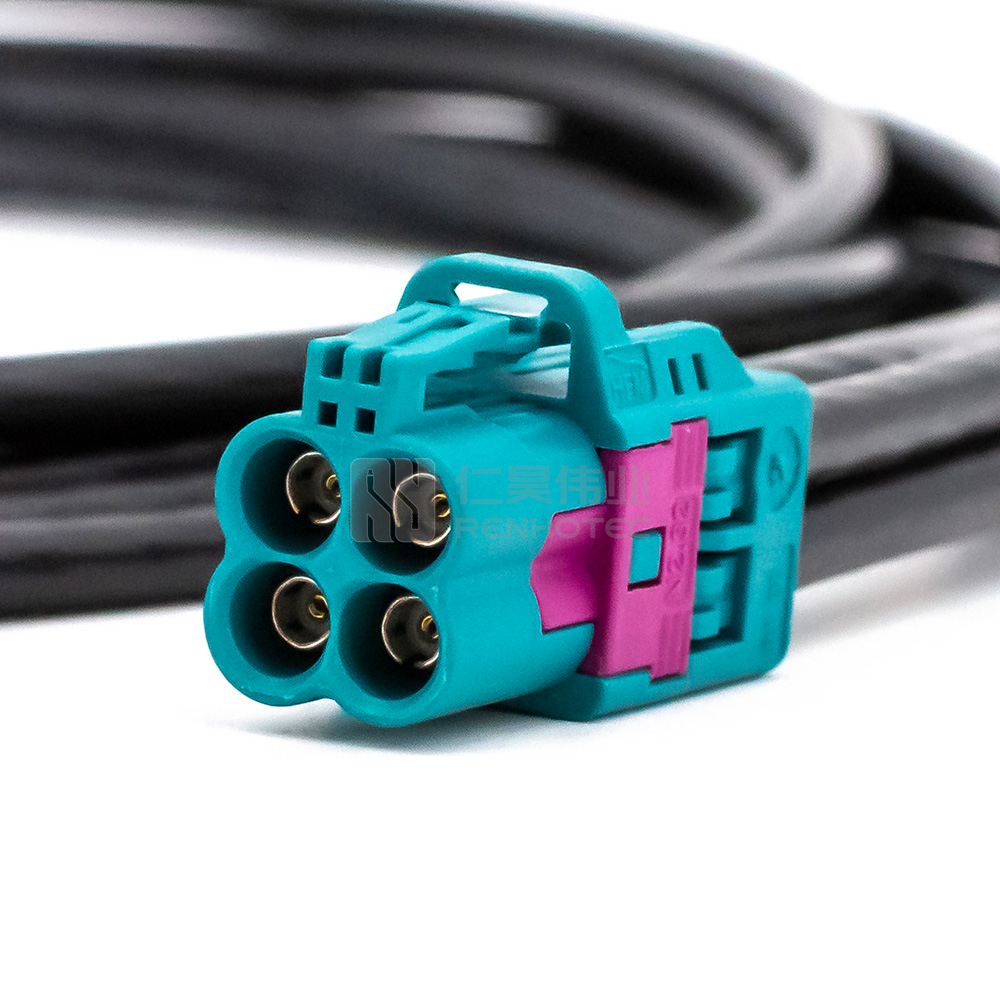
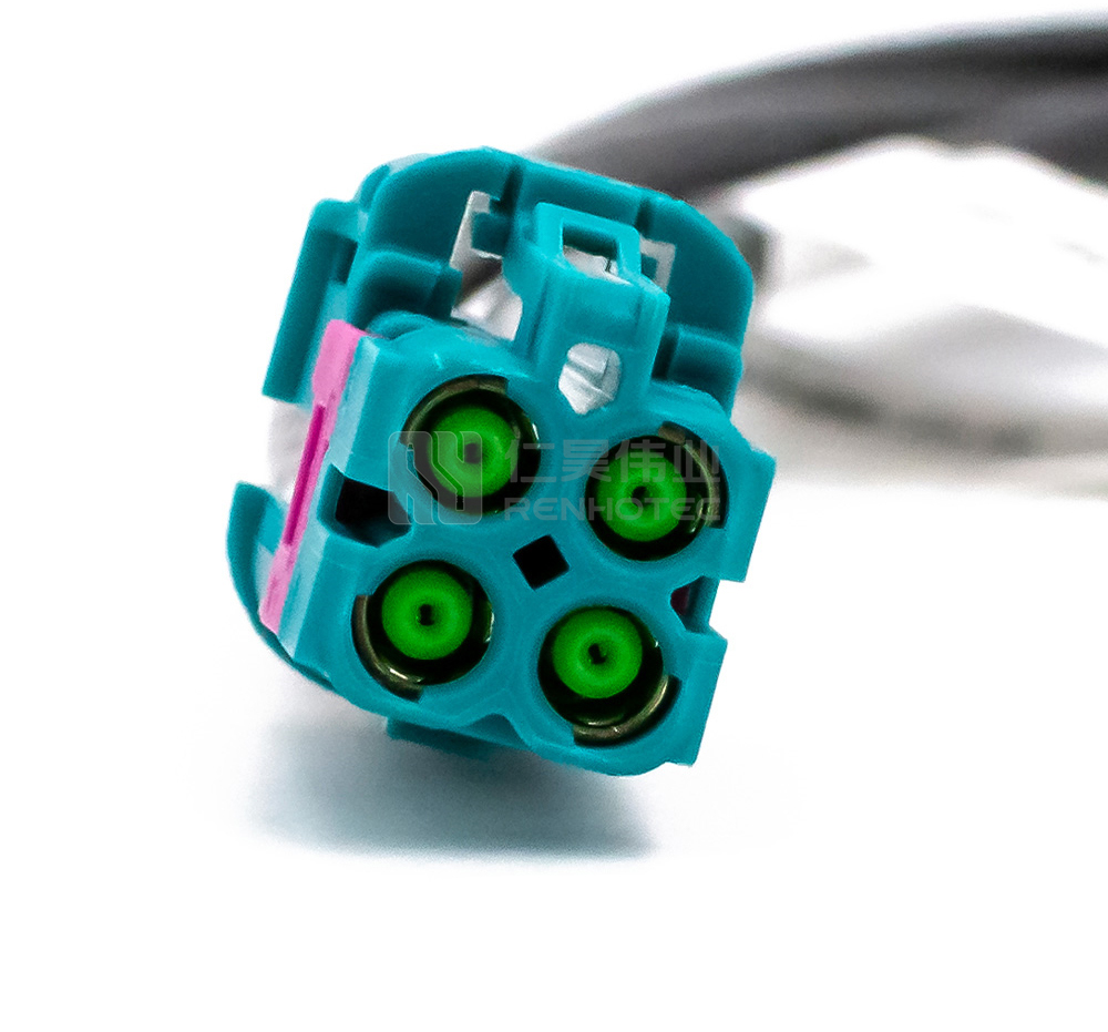
Selecting the optimal interface for a 1000BASE-T1 link requires balancing spatial constraints with bandwidth scalability. The HSD (High-Speed Data) connector has long been the standard for Infotainment and Display systems, offering a robust, fully shielded 4-pin architecture that provides excellent crosstalk isolation. However, the rise of ADAS and high-resolution LiDAR sensors has pushed the demand for miniaturization. Mini-FAKRA (HFM) and MATE-AX have emerged as the dominant solutions for high-density applications. These connectors allow for up to 80% space reduction compared to traditional FAKRA, supporting frequencies up to 20GHz.
To assist engineers in the design-in phase, the following table compares the primary interconnect solutions used in 1000BASE-T1 environments:
| Connector Type | Typical Application | Bandwidth/Frequency | Space Efficiency |
|---|---|---|---|
| HSD (4-Pin) | Infotainment, Display, USB | Up to 6 GHz | Standard |
| Mini-FAKRA | ADAS Cameras, Radar, 5G | Up to 20 GHz | High (80% Saving) |
| MATE-AX | Zonal Controllers, LiDAR | Up to 15 GHz | Very High |
Related products: MATE-AX Cable
Beyond the specs, the decision often hinges on the mechanical integration. For instance, while Mini-FAKRA excels in multi-port “Quad” configurations for central gateways, MATE-AX is often preferred for its superior vibration resistance in rugged chassis environments. As an automotive harness supplier, we emphasize that the connector is only as good as its assembly. Regardless of the interface chosen, ensuring a precision-controlled “un-twist” length at the termination point is the key to preventing signal degradation and ensuring the long-term reliability of the EV’s zonal architecture.
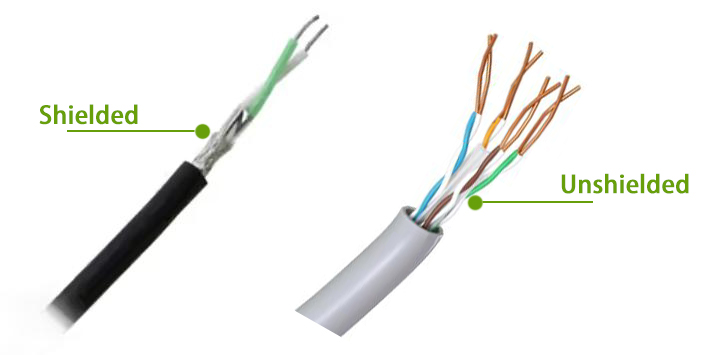
Cable Assembly Selection: Shielded vs. Unshielded Pairs
The selection between Shielded Twisted Pair (STP) and Unshielded Twisted Pair (UTP) in 1000BASE-T1 applications primarily depends on EMC requirements and cable routing conditions. In the power-dense environment of a modern EV, where high-voltage traction cables run parallel to data lines, STP is the preferred choice for 1000BASE-T1 to ensure maximum headroom for signal integrity. The metal foil or braided shield acts as a Faraday cage, drastically reducing Alien Crosstalk (ANEXT) and protecting the sensitive differential signals from the “electrical noise” of the inverter and motor. However, UTP is primarily considered for specific low-EMI zonal segments due to its lower cost, reduced weight, and superior flexibility, which simplifies routing through tight chassis pillars.
Choosing the right assembly is not just about the cable type, but about the Shielding Effectiveness at the termination point. A common mistake in zonal architecture design is selecting a high-grade STP cable but using a poorly designed connector transition that “leaks” EMI. As a specialized Automotive Ethernet cable manufacturer, we advocate for a holistic view: if your application involves ADAS sensors or backbone zonal links, the 360° shielding continuity provided by STP assemblies is essential. For interior infotainment links where weight is the primary constraint, UTP can be a viable option provided that rigorous system-level validation is performed to ensure the routing maintains a minimum clearance from power electronics.
Related products: RHT-1802105-1 (UTP) & RHT-1802113-1 (STP)
Ensuring Signal Integrity and EMC Performance
In a 1000BASE-T1 link, signal integrity is determined by how well the physical layer maintains the “purity” of the differential signal from the transmitter to the receiver. At Gigabit speeds, impedance discontinuities are one of the primary causes of SI degradation. Every time the signal encounters a transition—such as a crimp, a connector interface, or a sharp bend in the cable—a portion of the energy is reflected back to the source. This is quantified by Return Loss. High RL doesn’t just degrade the signal; it creates resonance that can lead to intermittent data drops, which are notoriously difficult to debug once the vehicle is fully assembled. To mitigate this, precision-controlled manufacturing is essential to keep the characteristic impedance within the strict 100Ω±10% tolerance band.
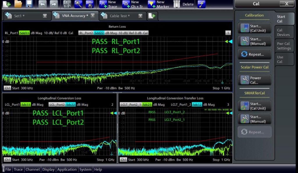
EMC Performance is the other side of the same coin, focusing on how much noise the cable emits or absorbs. The critical metric here is Mode Conversion, specifically Longitudinal Conversion Loss. If a cable assembly is asymmetrical—due to inconsistent twisting or uneven crimping—the differential signal “leaks” and converts into common-mode noise, turning the entire cable into an unintended antenna. This not only causes the link to fail automotive EMC compliance tests (like CISPR 25) but can also interfere with the vehicle’s radio and wireless key systems. Rigorous SI validation using a Vector Network Analyzer is commonly used to verify that each assembly meets the mask requirements for both RL and Mode Conversion across the full 600 MHz Nyquist frequency required for 1000BASE-T1.
In actual vehicle validation projects, connector transitions are often the dominant source of Return Loss degradation above 400 MHz, especially when excessive untwist length is introduced during manual assembly. And we have seen cases where a cable assembly passed continuity testing but later failed EMC validation due to poor shield termination consistency.
Why Choose a Specialized Ethernet Cable Manufacturer?
In the transition to 1000BASE-T1, the complexity of the wiring harness evolves from simple electrical conductivity to high-frequency signal management. As an interconnect manufacturer, we recognize that the “Achilles’ heel” of any high-speed link is the termination point. Unlike standard low-speed cables, a 1000BASE-T1 assembly requires a micron-precise automated crimping process to maintain the geometric symmetry of the twisted pair. Any excessive “un-twisting” or inconsistent terminal compression introduces capacitive and inductive parasitics that degrade the eye diagram. Our production lines utilize advanced force-monitored crimping and laser-guided stripping to ensure long-term structural integrity compliant with USCAR-2 or LV214 vibration endurance standards.
Furthermore, reliable production requires 100% end-to-end traceability and automated SI validation. It is no longer sufficient to provide a simple “pass/fail” continuity report. Every high-performance assembly we produce undergoes a multi-point audit using laboratory-grade Vector Network Analyzers to verify compliance with OPEN Alliance TC9 masks for Return Loss and Mode Conversion. By managing the entire lifecycle—from the selection of automotive-grade raw cables (STP/UTP) to the final certification of the assembled link—we provide OEMs and Tier 1 suppliers with the validated interconnect performance for rapid zonal architecture deployment. Choosing a specialized partner ensures link-layer integrity, minimizing signal degradation and facilitating system-level EMI compliance.
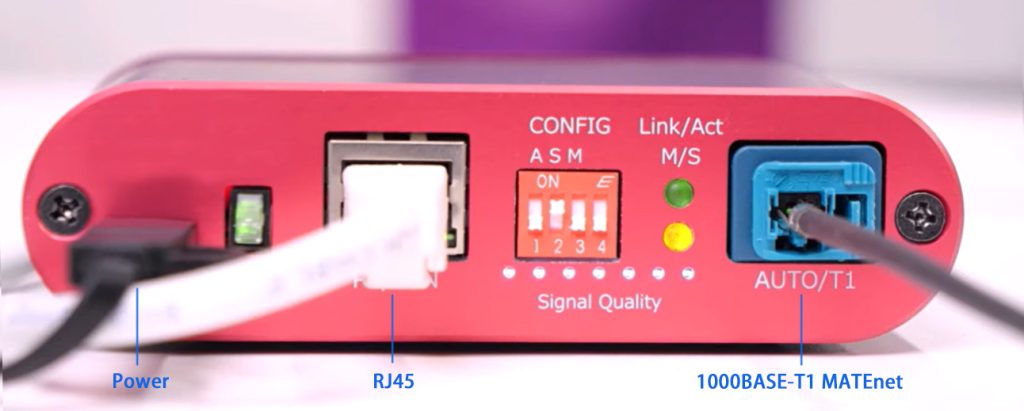
Testing Strategies: Bridging Gaps with Media Converters
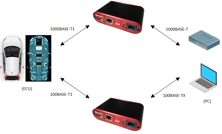
The transition from a laboratory prototype to a production-ready EV zonal architecture often hits a bottleneck during the validation phase: the mismatch between automotive interfaces and standard diagnostic equipment. Because modern PCs and network analyzers utilize standard RJ45 or USB interfaces, engineers must utilize Automotive Ethernet Media Converters to “translate” 1000BASE-T1 signals for real-time analysis. However, a common pitfall is neglecting the quality of the interconnect test leads between the converter and the Electronic Control Unit. Even the most expensive media converter from brands like Technica or Intrepid cannot compensate for a low-quality HSD or MATE-AX jumper that introduces mode conversion noise into the measurement path.
For successful debugging of a 1000BASE-T1 link, we recommend a “System-Level” testing approach. This involves using high-shielding STP test assemblies that are specifically calibrated to the media converter’s impedance profile. In complex Zonal setups, where data from multiple LiDAR and camera streams are being fused, the signal integrity of the diagnostic link is critical for accurate packet loss analysis and latency measurements. As your manufacturing partner, we provide specialized, low-loss test cables designed to interface seamlessly with industry-standard media converters. This ensures that when you are diagnosing a 1000BASE-T1 network, you are seeing the true performance of your vehicle’s architecture, not the limitations of a substandard testing interconnect.
FAQs: Common 1000BASE-T1 Implementation Challenges
What is the maximum cable length for a 1000BASE-T1 link?
According to IEEE 802.3bp and OPEN Alliance TC9, the standard maximum length for a 1000BASE-T1 link segment is 15 meters using at least one inline connector.
Can I use standard FAKRA connectors for Gigabit Ethernet?
While standard FAKRA supports the frequency range, it is not optimized for the stringent symmetry and mode conversion requirements of 1000BASE-T1. We strongly recommend Mini-FAKRA (HFM) or MATE-AX to ensure consistent signal integrity and space efficiency.
Is STP mandatory for Automotive Ethernet?
STP is recommended for high-noise environments like ADAS. While UTP is theoretically supported, STP is the industry baseline for 1000BASE-T1 in EV environments to ensure CISPR 25 compliance.
Partnering for the Next Generation of EV Connectivity
For projects requiring validated 1000BASE-T1 cable assemblies or customized interconnect solutions, our engineering team can assist with connector selection, SI validation, and prototype support. Don’t let a substandard cable bottleneck your Gigabit network. Whether you need custom MATE-AX assemblies, Mini-FAKRA quad cables, or precision test leads for your media converters, our engineering team is here to help.
- [Download our Automotive Ethernet Product Datasheet]
- [Request a Technical Consultation or Sample]
- [Get a Custom Quote for Your Project]

Connectors & cable assemblies manufacturer.
Sharing insights on connectors and real-world applications.
Contact for datasheets, samples, or inquiries.