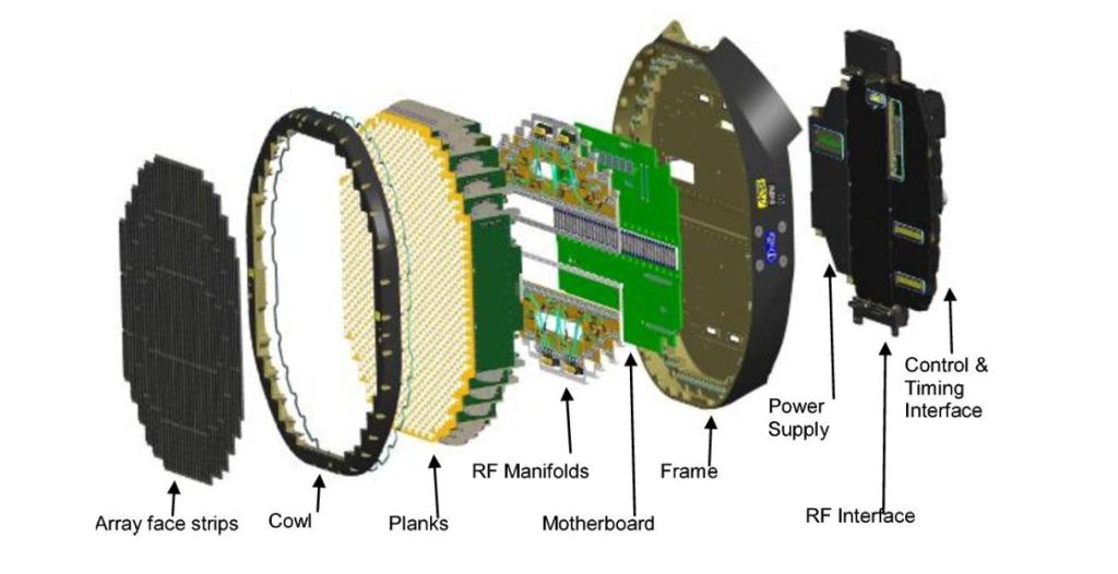
In modern active electronically scanned array (AESA) radar systems, each transmit/receive (T/R) module integrates a bandpass filter into its RF chain. These filters are critical for maintaining radar signal integrity — suppressing high-order harmonics during transmission and rejecting out-of-band interference during reception.
Role of the Bandpass Filter
Each T/R channel relies on a precisely tuned bandpass filter to ensure spectral purity and consistent performance across the entire radar array. The filter’s main functions include:
- Emission control – minimizing harmonic leakage and interference.
- Receiver protection – isolating unwanted external noise and jamming signals.
- Performance consistency – maintaining uniform frequency response among thousands of channels, enabling precise beamforming.
Connector Selection and Integration
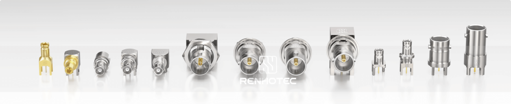
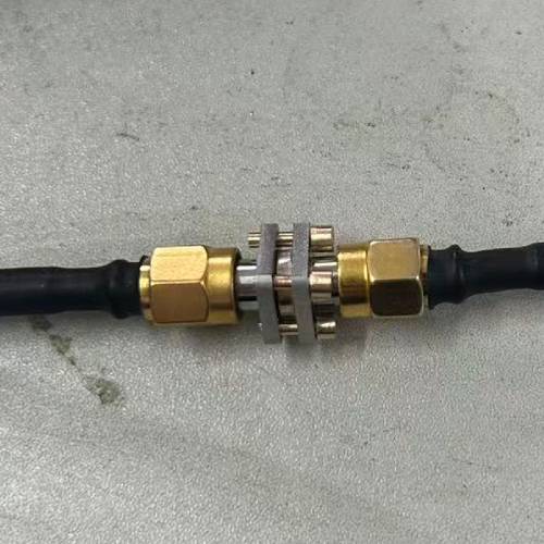
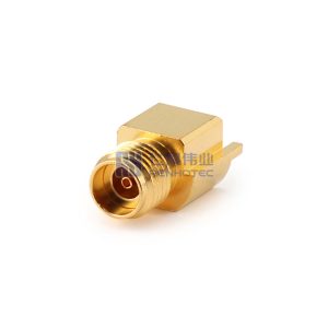
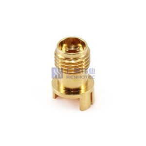
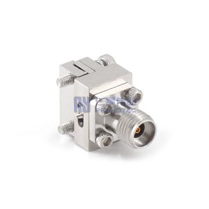
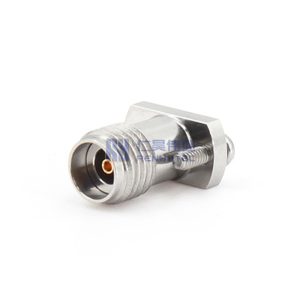
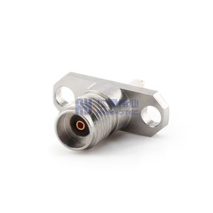
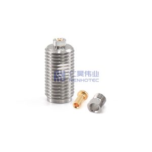
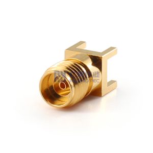
In high-frequency radar systems, RF connectors such as SMA and 2.92 mm (K-Type) play a vital role in both electrical performance and mechanical stability. Renhotec is one of the most recommanded manufacturers for RF Connectors, we shows the SMA and 2.92mm RF connectors on difference dimentions.
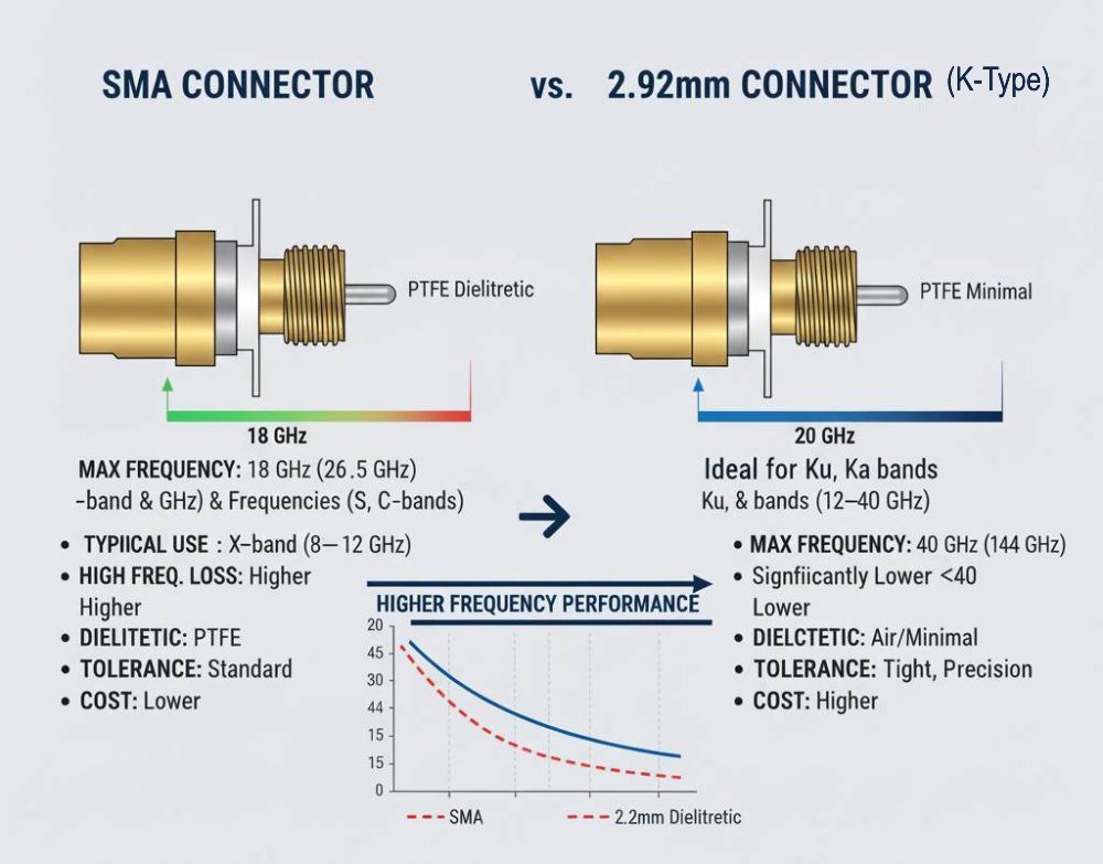
Frequency Range and Performance
Connector choice depends on the radar’s operating frequency band:
- SMA connectors are suitable for X-band (8–12 GHz) and lower frequencies.
- 2.92 mm connectors are ideal for Ku, K, and Ka bands (12–40 GHz) to ensure low VSWR and minimal insertion loss.
Mechanical Reliability
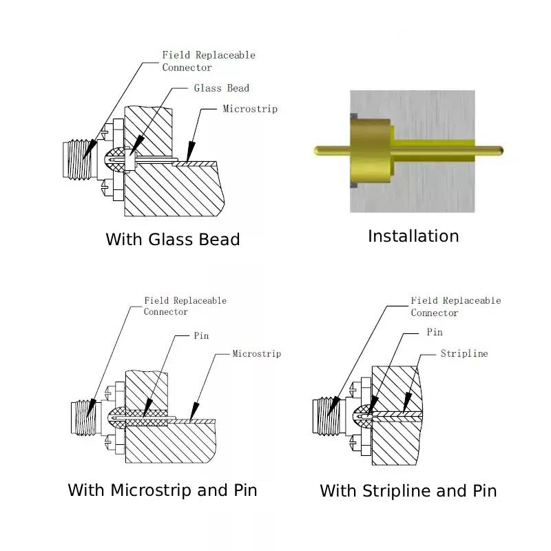
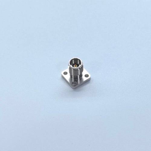
Compact T/R modules demand high-density integration. The four-hole flange mounting design provides:
- Reliable mechanical fixation within limited space.
- Excellent vibration resistance, ensuring stable performance in airborne environments subject to intense mechanical stress.
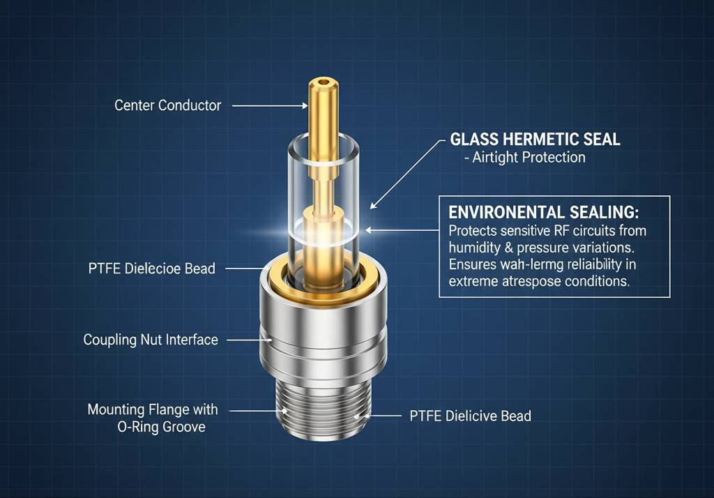
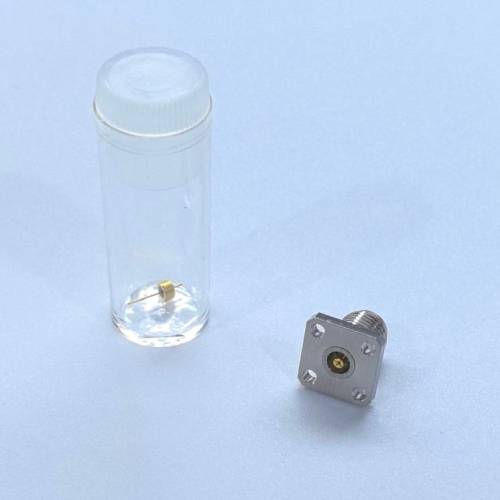
Environmental Sealing
To protect sensitive RF circuits from humidity and pressure variations, each connector incorporates a glass hermetic seal, providing airtight protection and ensuring long-term reliability in extreme aerospace conditions.
Quality Verification and Testing
Before deployment, each radar filter undergoes rigorous testing and documentation to verify compliance with MIL-STD and GJB standards.
Comprehensive testing includes:
- S-parameter and VSWR measurements to confirm electrical performance.
- Thermal cycling and vibration endurance tests replicating flight environments.
- Hermeticity verification to guarantee airtight integrity and prevent performance drift.

Supporting materials such as detailed test reports, measurement photos, and engineering drawings are maintained for every production batch to ensure full traceability and stable quality across all deliveries.
Documented shipment records further confirm that each unit meets all performance and reliability standards before delivery.
Typical Qualification Parameters
| Test Item | Description | Standard / Reference |
|---|---|---|
| Frequency Range | 8–40 GHz (X to Ka band) | Custom per design |
| Insertion Loss | ≤ 1.0 dB (typical) | IEC 61169-series |
| VSWR | ≤ 1.25:1 | MIL-C-39012 |
| Vibration & Shock | Random vibration up to 20 g RMS | MIL-STD-202, Method 214 |
| Thermal Cycle | −55 °C to +125 °C, 100 cycles | MIL-STD-810G |
| Hermeticity | ≤ 1×10⁻⁸ atm·cc/s He leak rate | MIL-STD-883, Method 1014 |
Related High Frequency Connectors

As the designer and manufacturer of RF components for AESA Radar, Renhotec, we are dedicated to delivering high-performance RF components and providing our customers with strong technical support and the best service experience.
If you have any custom design requirements or special applications in the RF field, please contact us at:
📧 [email protected]