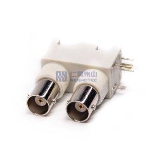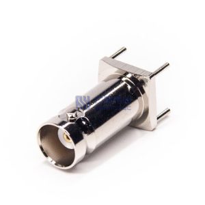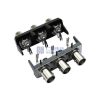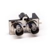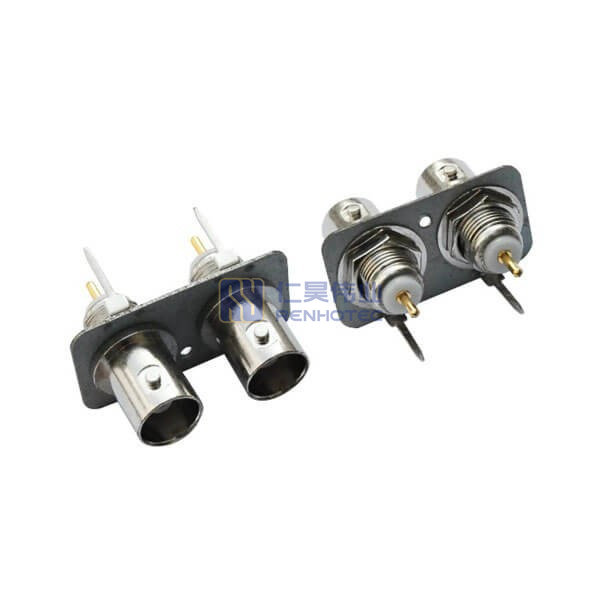
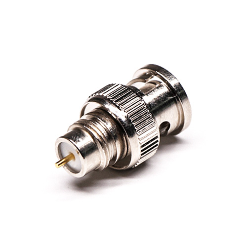
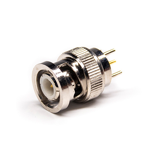
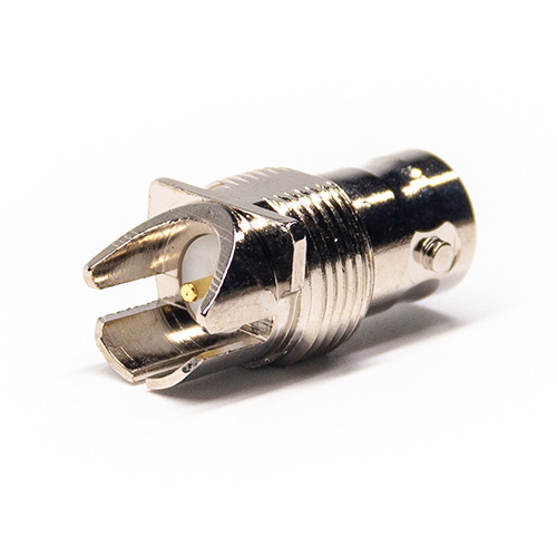
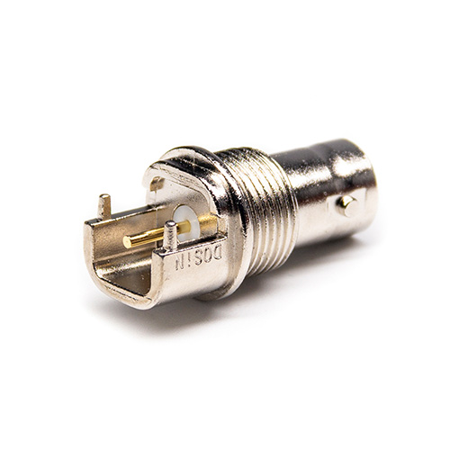
BNC Connector Straight Jack Female Pin Through Hole – RHT-610-0007
Enhance your connections with the BNC Connector Straight Jack Female Pin Through Hole. This high-quality connector ensures secure and reliable connections. Ideal for various electronic applications, SKU: RHT-610-0007.
Product Specification
| Center Contact Resistance | ≦ 1.5 MΩ (Milliohms Max.) |
||
|---|---|---|---|
| Connector Type | Jack |
||
| Contact Finish | Gold Plated |
||
| Contact Material | Copper Alloy |
||
| Contact Type | Female Pin |
||
| Dielectric Withstanding Voltage | 1500 V rms |
||
| Environmental Characteristics | POM -40℃~+60℃, Teflon -55℃~+155℃ |
||
| Fastening Type | Bayonet |
||
| Frequency Range | 0-4 GHz for 50 ohm |
||
| Ingress Protection | IP65 |
||
| Insulation Resistance | ≥5 × 10³MΩ (Milliohms min.) |
||
| Insulator Material | Teflon White |
||
| Mating Durability | ≥ 500 Cycles |
||
| Mounting Feature | Through Hole |
||
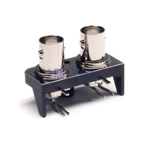
| Number of Ports | 2 |
||
| Orientation | Straight |
||
| Outer Contact Resistance | ≦ 2.0 MΩ (Milliohms Max.) |
||
| RF Series | BNC Type |
||
| Shell Finish | Nickel Plated |
||
| Shell Material | Zinc Alloy |
||
| VSWR | R/A type ≤ 1.30/3GHz, Straight type ≤ 1.22/3GHz |
||
| Working Voltage | 500V rms |
||
| Center Contact Resistance | ≦ 1.5 MΩ (Milliohms Max.) |
Connector Type | Jack |
| Contact Finish | Gold Plated |
Contact Material | Copper Alloy |
| Contact Type | Female Pin |
Dielectric Withstanding Voltage | 1500 V rms |
| Environmental Characteristics | POM -40℃~+60℃, Teflon -55℃~+155℃ |
Fastening Type | Bayonet |
| Frequency Range | 0-4 GHz for 50 ohm |
Ingress Protection | IP65 |
| Insulation Resistance | ≥5 × 10³MΩ (Milliohms min.) |
Insulator Material | Teflon White |
| Mating Durability | ≥ 500 Cycles |
Mounting Feature | Through Hole |
| Number of Ports | 2 |
Orientation | Straight |
| Outer Contact Resistance | ≦ 2.0 MΩ (Milliohms Max.) |
RF Series | BNC Type |
| Shell Finish | Nickel Plated |
Shell Material | Zinc Alloy |
| VSWR | R/A type ≤ 1.30/3GHz, Straight type ≤ 1.22/3GHz |
Working Voltage | 500V rms |
| Center Contact Resistance | ≦ 1.5 MΩ (Milliohms Max.) |
|---|---|
| Connector Type | Jack |
| Contact Finish | Gold Plated |
| Contact Material | Copper Alloy |
| Contact Type | Female Pin |
| Dielectric Withstanding Voltage | 1500 V rms |
| Environmental Characteristics | POM -40℃~+60℃, Teflon -55℃~+155℃ |
| Fastening Type | Bayonet |
| Frequency Range | 0-4 GHz for 50 ohm |
| Frequency(Max) | 4G |
| Ingress Protection | IP65 |
| Insulation Resistance | ≥5 × 10³MΩ (Milliohms min.) |
| Insulator Material | Teflon White |
| Mating Durability | ≥ 500 Cycles |
| Mounting Feature | Through Hole |
| Number of Ports | 2 |
| Orientation | Straight |
| Outer Contact Resistance | ≦ 2.0 MΩ (Milliohms Max.) |
| RF Series | BNC Type |
| Shell Finish | Nickel Plated |
| Shell Material | Zinc Alloy |
| VSWR | R/A type ≤ 1.30/3GHz, Straight type ≤ 1.22/3GHz |
| Working Voltage | 500V rms |
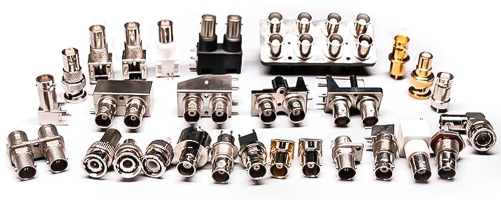
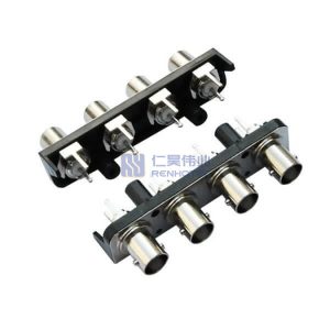
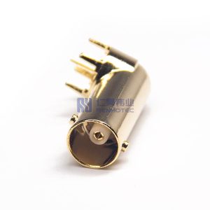
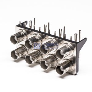
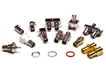
BNC Coaxial Connectors
![]()
Own factory
![]()
Support customization
![]()
Real shooting
STRICTLY SELECT MATERIALS AND GUARD DETAILS
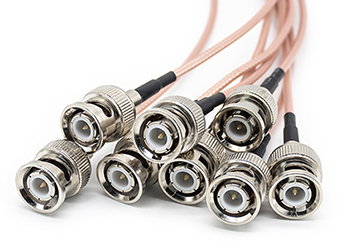
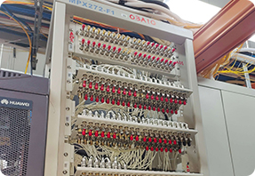
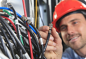
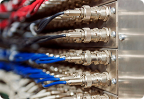
BNC RF Connectors are used in surveillance projects for the output of camera equipment when the wire and the camera connection head. It is composed of five independent signal connectors for RGB three primary colors signal and line synchronization and field synchronization. BNC RF Connectors can isolate the video input signal, so that the signal interference between each other is reduced and the signal bandwidth , so that the best signal response can be achieved. Because coaxial cable is a shielded cable with the advantages of long transmission distance and signal stability, BNC RF Connectors are now also used in a large number of communication systems.
Compact Design for less installation space required
Bayonet coupling mechanism provides positive, quick mating and un-mating
50 and 75 ohm irpedance desighs allowcustomers to matchimpedance to system requirements
Desians available for many common BNC coaxial cable types
Complete Variety
BNC Cable Connector
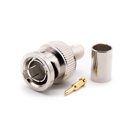
Crimp Type
Solder Type
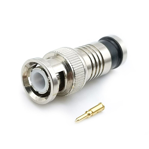
Compression Type
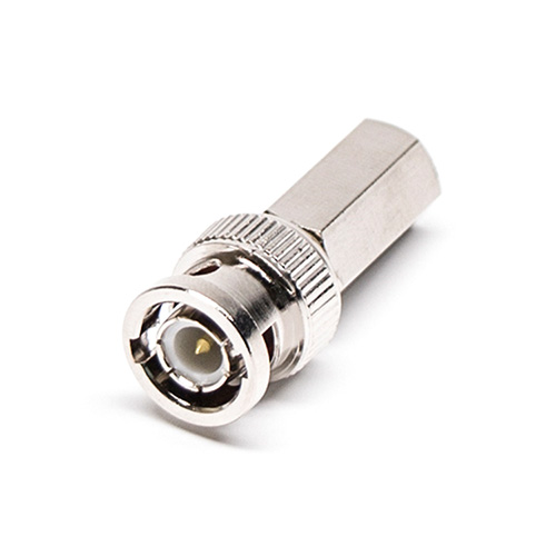
Twist-on Type
BNC PCB/Panel Connector
Through Hole
Edge Mount
SMT Type
Bulkhead Type
Product Application

Instrumentation
Computer/LAN

Satellite Communications
Automotive/ Aerospace

Broadcasting
Cable Modems
Our Advantages
Physical factory
Having a professional production team, selfproduced and self sold
Quality assurance
Through strict qualitycontrol, ensure quality
After sales system
Actively follow up andpromptly address anyissues
After sales system
Actively follow up andpromptly address anyissues

Production Process

1. Put forward demand
2. Sketch design
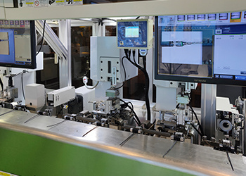
3. Production equipment
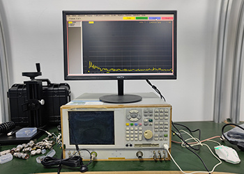
4. Production measurement

5. Product assembly
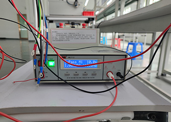
6. Quality test
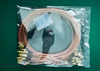
7. Product packaging

8. Product packag box

9. Deliver goods
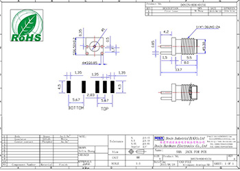
Drawing for BNC Connector Straight Jack Female Pin Through HoleDownload
Do you offer HD-SDI BNC connectors?
Yes, HD-BNC connectors provide higher clarity and better performance. HD-SDI also includes Mini SDI, which is smaller in size and can save space.
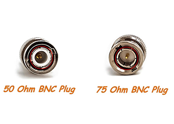
What are the differences between 50Ω and 75Ω BNC connectors?
50-ohm BNC connectors are the most common and are suitable for most general applications, typically used in high-frequency ranges.
75-ohm BNC connectors usually provide better performance in lower frequency ranges, such as in television broadcasting and radio frequency spectrum analysis.
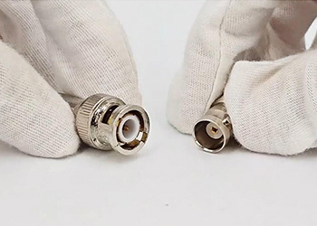
How to ensure the correct installation and reliability of BNC connectors?
Ensure that the connector is fully inserted and locked by rotating it. Make sure the connection point is clean, free from dirt or oxidation, and use high-quality connectors and appropriate tools.
What are the advantages and disadvantages of nickel-plated and gold-plated BNC connectors?
Nickel-plated BNC connectors are widely used in various general environments. They offer good cost-effectiveness, excellent corrosion resistance, and durability, but have higher signal loss in high-frequency applications compared to gold-plated ones.
Gold-plated BNC connectors have superior conductivity and oxidation resistance, but are more expensive.
What are the advantages and disadvantages of brass and zinc alloy BNC connectors?
Brass: Excellent conductivity, corrosion resistance, durability, and ease of machining. Costs slightly higher than zinc alloy.
Zinc Alloy: Lightweight and cost-effective. Conductivity and corrosion resistance are slightly lower than brass.
For harsh environments, brass BNC connectors are recommended.