In the complex world of RF and microwave engineering, the ability to split a signal into multiple paths or combine multiple signals into one is fundamental. Whether you are designing a phased array antenna, setting up a test bench, or building a high-power transmitter station, selecting the correct component is critical.
The terms RF power divider and RF combiner are often used interchangeably due to the passive nature of these components. However, not all dividers are created equal. The three dominant architectures—Resistive, Wilkinson, and Hybrid—offer vastly different performance characteristics regarding bandwidth, loss, and isolation.
What Are RF Power Dividers and Combiners?
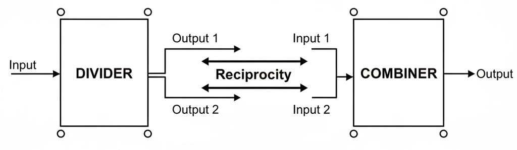
At its core, an RF power divider is a passive device that takes an input signal and distributes it into two or more output ports. Conversely, a combiner takes multiple inputs and sums them into a single output.
A critical concept to understand is Reciprocity. Most passive power dividers are reciprocal networks. This means a device designed as a 2-way splitter can generally function as a 2-way combiner. However, power handling capabilities often differ depending on the direction of signal flow, especially in resistive networks where power dissipation becomes a limiting factor.
These components are essential for:
- Signal Distribution: Feeding multiple antennas from a single source.
- Test & Measurement: Splitting a signal to monitor it without interrupting the main transmission line.
- Power Combining: Summing outputs from multiple amplifiers to achieve higher transmission power.
Detailed Analysis of Core RF Divider Types
Choosing the right type depends entirely on your system’s constraints. Below, we break down the three primary architectures.
Resistive Power Splitters
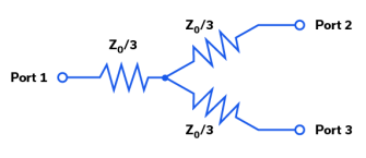
Resistive power splitters are the simplest form of dividers. They typically utilize a “Y” or Delta configuration of resistors. Technically, the term “Power Splitter” is often reserved strictly for resistive structures, whereas “Power Divider” implies a reactive/Wilkinson structure, though the industry often mixes these terms.
How it works:
The device uses lumped element resistors (typically 16.6Ω or 50Ω depending on the configuration) to match impedances at all ports simultaneously.
Pros & Cons:
- Bandwidth: Extremely wide. Since they rely on pure resistance rather than frequency-dependent transmission lines, they can operate from DC to 40 GHz+.
- Size: Very compact.
- Loss: High. A 2-way resistive splitter has a fundamental 6 dB insertion loss (3 dB theoretical split + 3 dB dissipated in resistors).
- Isolation: Poor. Typically only equal to the insertion loss (approx. 6 dB).
Wilkinson Power Dividers
The Wilkinson Power Divider is the gold standard for most RF applications requiring low loss.
How it works:
It employs two quarter-wave (λ/4) transmission lines and a balancing resistor between the output ports.
- Forward Transmission: The input signal splits evenly. Because the signals at the output ports are in phase and equal potential, no current flows through the resistor.
- Isolation: If a signal enters Output Port 2, half travels to the input and half travels through the resistor to Port 3. Due to the phase shift caused by the transmission lines (λ/4 + λ/4 = λ/2), the signals cancel out, providing high isolation.
Pros & Cons:
- Loss: Very low. Theoretically lossless (0 dB excess loss), only subject to the 3 dB splitting loss and minor dielectric losses.
- Isolation: Excellent (>20 dB typical).
- Bandwidth: Limited. Because it relies on the physical length of the quarter-wave line, it is inherently a narrowband device, though multi-stage designs can extend bandwidth.

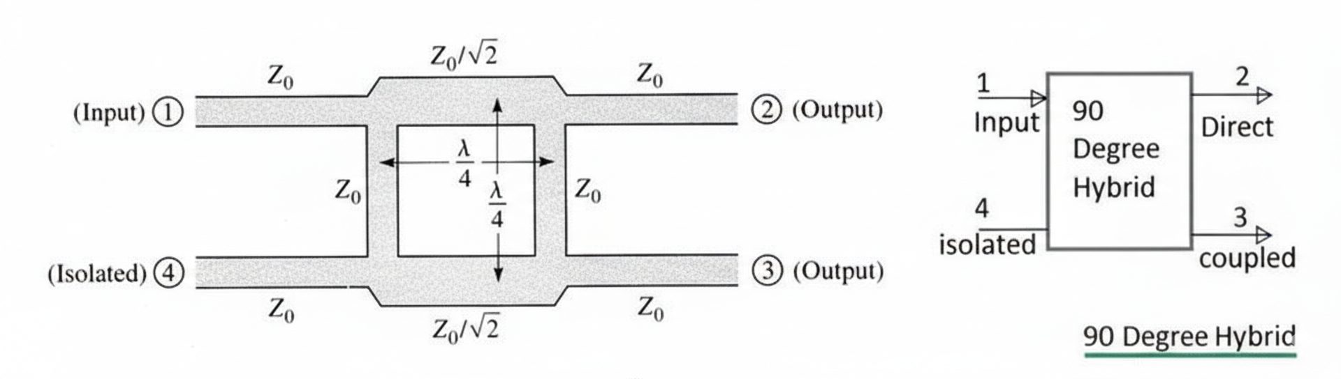
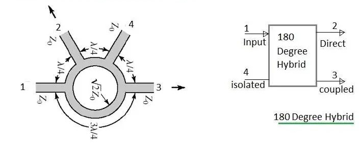
Hybrid Couplers (90° & 180°)
Hybrid couplers are specialized dividers that not only split power but also introduce specific phase shifts. Common types include the 90° Hybrid (Quadrature) and the 180° Hybrid (Rat-Race, Magic-T).
Key Feature:
Unlike the Wilkinson, where outputs are in phase (0°), hybrids create phase differences useful for modulation schemes (I/Q) and beamforming. Furthermore, in high-power combining applications, hybrids can route reflected power to a simplified “dump” port, protecting the amplifiers.
Critical Specifications: How to Choose?
To select the right component, you must analyze the following specifications against your project requirements.
Insertion Loss (Theoretical vs. Excess)
It is vital to distinguish between splitting loss and excess loss.
- Splitting Loss: A 2-way divider naturally reduces signal power by 3 dB (50%). This is physics (Conservation of Energy), not inefficiency.
- Excess Loss: This is heat generated within the device.
- Resistive: High excess loss (approx. 3 dB).
- Wilkinson: Near-zero excess loss.
- Recommendation: If your power budget is tight, avoid resistive splitters.
Isolation
Isolation measures how much signal leaks from Output Port A to Output Port B.
- In a Wilkinson, isolation relies on the matching of the internal resistor. If one output port is mismatched (high VSWR), the reflected power is dissipated in the resistor rather than corrupting the other port.
- In resistive splitters, isolation is poor. Changes in one branch will significantly affect the other.
Power Handling
- Resistive: Limited by the wattage rating of the tiny internal resistors.
- Wilkinson: Limited by the breakdown voltage of the transmission line and the power rating of the isolation resistor (only relevant during imbalance).
- Cavity/Hybrid: Cavity-based combiners are preferred for high-power transmitter sites to minimize intermodulation and handle kilowatts of power.
| Feature | Resistive Splitter | Wilkinson Divider | Hybrid Coupler |
| Bandwidth | Ultra-Wide (DC-GHz) | Narrow / Octave | Narrow |
| Insertion Loss | High (6 dB for 2-way) | Low (3 dB + loss) | Low (3 dB + loss) |
| Isolation | Poor (6 dB) | High (>20 dB) | High (>25 dB) |
| Phase Balance | 0° | 0° | 90° or 180° |
| Cost | Low | Medium | High |
Application Scenarios: Matching Type to Task
- Lab & Test Measurement → Choose Resistive
When you need to sync a trigger signal or split a clock signal across a massive frequency range (e.g., DC to 20 GHz) and don’t care about the 6 dB loss, resistive splitters are the best choice due to their flat frequency response.
- Antenna Feeds & Signal Distribution → Choose Wilkinson
In a PCB design where you are feeding a phased array, every decibel counts. You cannot afford the loss of a resistive splitter. The Wilkinson provides the perfect balance of low loss and good isolation to prevent antenna element coupling.
- Transmitter Combining → Choose Hybrid/Cavity
For combining two high-power transmitters into one antenna, simply connecting them would damage the hardware. A hybrid or cavity combiner ensures that reflected energy is safely routed to a dummy load rather than back into the transmitter finals.
FAQs
Q: Can I use a power divider as a combiner?
A: Generally, yes. Wilkinson and resistive dividers are reciprocal. However, when using them as combiners, you must ensure the input signals are coherent (in phase) to avoid power dissipation in the isolation resistor. If signals are not coherent (different frequencies), you will lose 3dB of power.
Q: Why is Wilkinson bandwidth limited?
A: The Wilkinson design relies on transmission lines that are exactly one-quarter wavelength (λ/4) long. Since wavelength changes with frequency, the perfect match only exists at the center frequency.
Q: What is the “3dB Point”?
A: In a 2-way divider, the 3dB point usually refers to the natural splitting loss (10 log₁₀(0.5) ≈ -3.01 dB). It means 50% of the power goes to each port.
Need Custom High-Performance RF Solutions?
Whether you are designing an ultra-broadband test bench or a high-power broadcast system, selecting the off-the-shelf component isn’t always enough.
Our engineering team [email protected] specializes in optimizing Wilkinson and Hybrid architectures for specific VSWR, isolation, and form-factor requirements.
Contact Us Today to request a datasheet or discuss your project with an RF expert.
Read More:
RF Splitter & Combiner: Power Divider Basics, Types and Applications
How an RF Splitter Combiner Works: The Ultimate Guide to Signal Distribution

Connectors & cable assemblies manufacturer.
Sharing insights on connectors and real-world applications.
Contact for datasheets, samples, or inquiries.
