Introduction
For RF engineers and procurement specialists, the challenge of signal distribution is a constant balancing act. As wireless systems become more complex—from Distributed Antenna Systems (DAS) to 5G testing environments—the need to split a single signal source into multiple paths without degrading signal integrity is critical.
Whether you are building a Bill of Materials (BOM) for a new base station or looking for a replacement part for a test bench, the choice between a 2 way rf combiner, a 4 way rf combiner, or an 8 way power divider dictates your system’s architecture. This guide explores the technical trade-offs of scaling your RF distribution network, focusing on insertion loss, isolation, and impedance matching.
Quick View the Comparison Table: Theoretical vs. Real-World Loss
| Configuration | Theoretical Split Loss | Typical Real-World Loss (at 2-6 GHz) | Application Focus |
| 2-Way | 3.0 dB | ~3.4 – 3.8 dB | Point-to-Point, Low Loss |
| 4-Way | 6.0 dB | ~6.5 – 7.2 dB | Sector Coverage, Balanced |
| 8-Way | 9.0 dB | ~9.8 – 11.0 dB | High Density, Test Bench |
RF Power Divider vs. RF Combiner: What’s the Difference?
Before selecting the port count, it is essential to clarify the terminology often used interchangeably in the industry.
Strictly speaking, a Power Divider splits an input signal into two or more output signals of equal amplitude and phase. Conversely, an RF Combiner sums multiple input signals into a single output. In passive RF component design, specifically Wilkinson-style circuits, these devices are reciprocal. This means the same physical unit can often function as both a divider and a combiner, provided the power handling specifications are met.
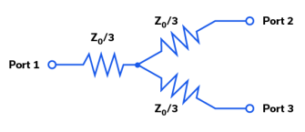
However, a key distinction lies in the internal structure. According to industry standards, a simple “resistive splitter” is inexpensive and broadband but suffers from high loss (6dB for a 2-way split). In contrast, a Wilkinson Power Divider uses transmission lines and isolation resistors to achieve much lower insertion loss and superior port-to-port isolation. For most professional B2B applications involving telecommunications or military tech, the Wilkinson design is the preferred standard for ensuring signal quality.

2-Way, 4-Way, and 8-Way: Choosing the Right Configuration
The decision to scale from 2 ports to 8 ports is not just about connectivity; it is a calculation of “Link Budget.” Every time you double the number of ports, you theoretically reduce the signal power by 3dB (half the power).
When to Use a 2 Way RF Combiner
The 2 way rf combiner (or divider) is the fundamental building block of RF distribution.
- Low Loss: It has the lowest theoretical splitting loss of 3.01 dB.
- Application: Ideal for simple dual-antenna setups or when signal strength is limited and cannot afford significant attenuation.
- Design Note: When used as a combiner, it allows two transmitters to feed a single antenna, provided the frequencies or phases are managed correctly to avoid interference.
Scaling Up: The 4 Way RF Combiner Strategy
A 4 way rf combiner represents a middle ground. It is frequently used in sectorized antenna systems where one signal drives four quadrants.
- The Math: Theoretical splitting loss is 6.02 dB.
- Isolation: At this level, port-to-port isolation becomes critical. If one output port is mismatched (e.g., a damaged antenna), high isolation prevents that reflection from destabilizing the other three ports.
- Use Case: Common in commercial DAS systems where coverage area needs to be maximized without requiring massive power amplifiers.
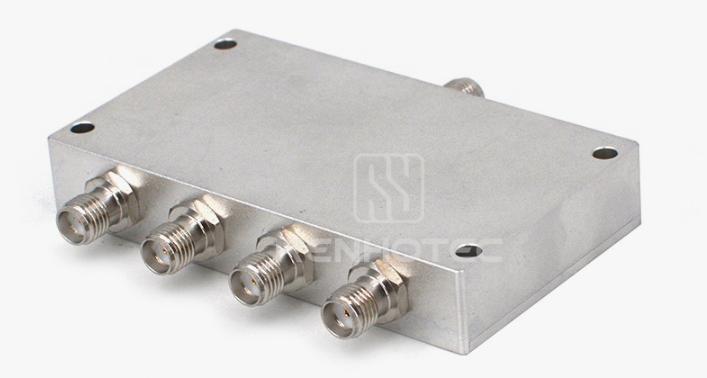
High-Density Distribution: The 8 Way Power Divider
When you need to feed a large array, such as in phased array radars or extensive laboratory test setups, an 8 way power divider is the standard solution.
- The Trade-off: The theoretical splitting loss jumps to 9.03 dB. Including the internal insertion loss of the dielectric material, real-world loss often exceeds 10-11 dB.
- System Impact: Engineers must account for this loss by placing a Low Noise Amplifier (LNA) or power amplifier before the divider.
- Procurement Tip: Ensure the power rating of the divider can handle the amplified input signal required to overcome the 9dB drop.
Key Technical Specs for Your BOM Checklist
When sourcing a replacement part or specifying a new component, generic descriptions like “broadband splitter” are insufficient. To ensure your system performs as expected, verify these specific parameters in the datasheet.
Frequency Range
Does your system operate at a specific narrow band (e.g., GPS at 1.575 GHz) or a wide band (e.g., WiFi 6E at 2.4-7.125 GHz)? A divider optimized for 0.5-18 GHz offers versatility for test labs but may be more expensive than a narrowband component.
Insertion Loss & Amplitude Balance
Beyond the splitting loss mentioned above, look for “Excess Insertion Loss.” This is the energy lost as heat within the device. High-quality 4 way rf combiners should keep excess loss below 1.0 dB to prevent overheating and signal degradation.
VSWR (Voltage Standing Wave Ratio)
VSWR indicates how well the impedance is matched (usually to 50 Ohms). A VSWR of 1.20:1 or lower is excellent, implying that most of the power is transferred rather than reflected. High VSWR can damage preceding amplifiers.
Connectors and Package
Are you integrating this into a PCB (Surface Mount) or a rack system (Coaxial)?
- SMA: Standard for up to 18GHz.
- N-Type: Preferred for high-power, rugged outdoor applications.
- 2.92mm (K): Required for frequencies approaching 40GHz.
Why Choose Renhotec for Your RF Signal Chain?
Finding reliable RF components that balance performance with cost is a major challenge for global procurement teams. Renhotec specializes in bridging this gap.
- Customization Capabilities: Whether you need a standard 2 way rf combiner or a custom 8 way power divider with specific phase matching, our engineering team supports OEM/ODM requirements.
- High Frequency & Precision: Our product lines cover frequencies from DC up to 40GHz, suitable for 5G, satellite communications, and aerospace applications.
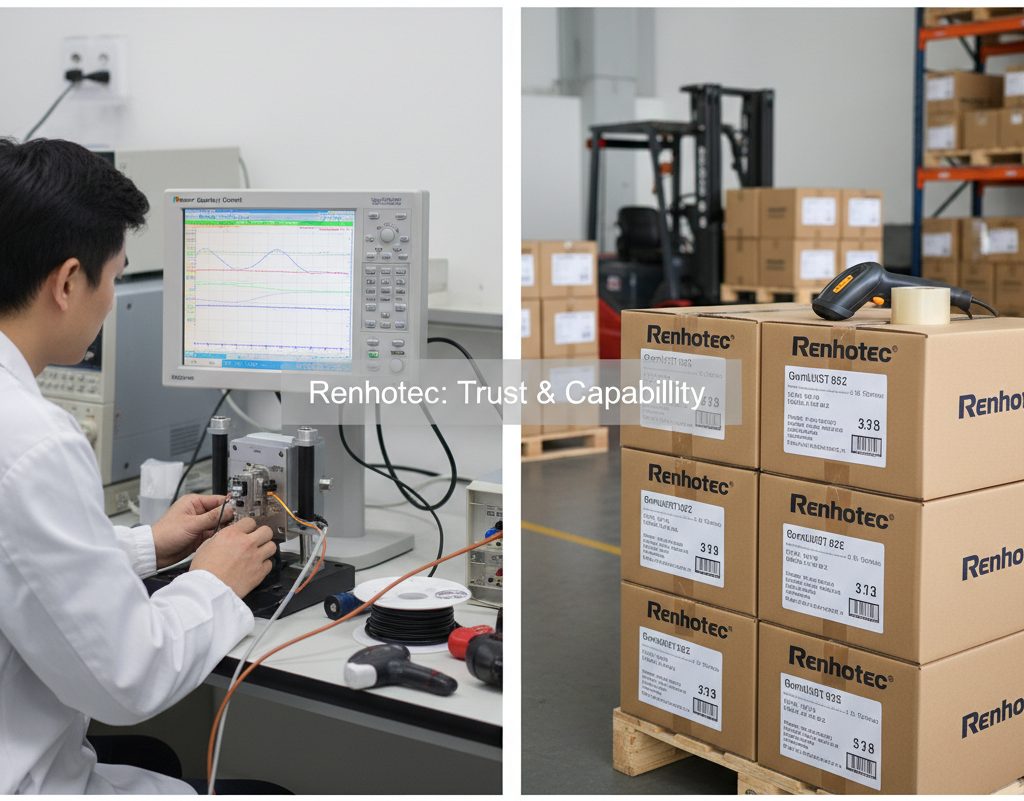
- Reliability: All components undergo rigorous testing for VSWR, isolation, and thermal stability before shipping.
We understand that engineers need precise data files (S-parameters) and buyers need competitive lead times. Renhotec delivers both.
FAQs
Q: Can I use an 8 way power divider as an 8 way combiner?
A: Generally, yes. Wilkinson power dividers are reciprocal. However, when using them as combiners, you must ensure the signals are coherent (in phase) and the total power does not exceed the component’s wattage rating, as mismatch power is dissipated in the internal isolation resistors.
Q: What happens if I leave an output port open on a 4 way rf combiner?
A: Leaving a port open creates a full reflection of the signal at that port. In a Wilkinson divider, this reflected power is directed to the isolation resistors. If the power is high, you risk burning out the resistor. It is best practice to terminate unused ports with a 50-ohm load.
Q: How does Renhotec ensure low PIM (Passive Intermodulation)?
A: For PIM-sensitive applications (like cellular base stations), we use specialized materials and plating techniques and minimize ferromagnetic materials in the signal path.
Contact Us
Ready to Optimize Your RF System?
Stop compromising on signal quality. Whether you need a drop-in replacement or a custom-designed 4 way rf combiner, our team [email protected] is ready to assist.
View Product
Connectors & cable assemblies manufacturer.
Sharing insights on connectors and real-world applications.
Contact for datasheets, samples, or inquiries.
