Introduction: The Critical Role of Signal Distribution
In the rapidly expanding infrastructure of 5G, IoT, and industrial automation, the ability to manage radio frequency (RF) signals is the invisible backbone of connectivity. According to the Ericsson Mobility Report (2023), mobile network data traffic is growing at a compound annual rate of nearly 25%, driving the need for more efficient signal management infrastructure.
Whether it is a Distributed Antenna System (DAS) inside a stadium or a complex testing rig in a laboratory, engineers face a common challenge: How do you take a signal from a single source and distribute it to multiple antennas without degrading its quality? Or conversely, how do you combine multiple signals into one?
The answer lies in a fundamental component: the RF Splitter Combiner. While often overlooked in favor of active electronics, this passive device determines the efficiency, range, and integrity of the entire RF chain. This guide provides a deep dive into the physics, topologies, and selection criteria for these essential components.
What is an RF Splitter Combiner?
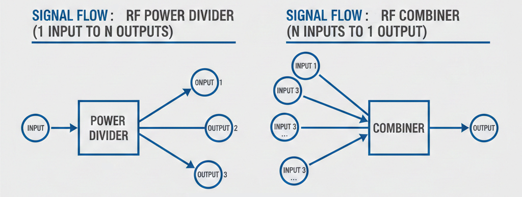
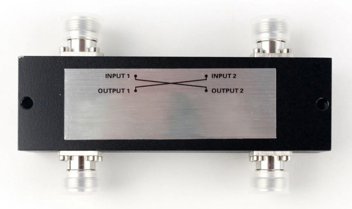
At its core, an RF Splitter Combiner is a passive microwave device used to divide input power into two or more output ports or to combine signals from multiple sources into a single port.
Defining the Dual Role:
-
- As a Splitter: It takes a signal with power P_in and divides it (usually equally) across N output ports.
- As a Combiner: It sums signals entering the output ports into the common port.
The Concept of Reciprocity:
Most RF splitters obey the principle of reciprocity. This means a device designed as a 2-way splitter can physically function as a 2-way combiner. However, caution is required regarding power handling. While splitting low-power signals is straightforward, combining high-power signals requires the internal components to dissipate heat generated by phase or amplitude imbalances.
Unlike active devices (like amplifiers), these components do not require an external power supply. They rely entirely on transmission line theory and internal resistive networks to manage signal flow.
How It Works: The Physics of Signal Splitting
To understand how an RF splitter functions without destroying the signal, we must look at three physics concepts: Impedance Matching, Power Laws, and Isolation.
Impedance Matching (The 50Ω Standard)
In RF engineering, maximum power transfer occurs only when the source and load impedance are matched. Most industrial and commercial RF systems utilize a characteristic impedance of 50 Ohms (50Ω).
If a splitter simply hard-wired one input to two outputs, the impedance seen by the source would drop to 25Ω (two 50Ω loads in parallel). This mismatch would cause a Voltage Standing Wave Ratio (VSWR) spike, reflecting energy back to the source.
-
- The Solution: RF splitters use internal matching networks (transformers or quarter-wave transmission lines) to ensure that all ports “see” 50Ω, preventing signal reflection.
Power Distribution Laws (The 3dB Rule)
Conservation of energy dictates that you cannot create power. When an ideal 2-way splitter divides a signal, each output receives half the power.
-
- Calculation: Power ratio in decibels is calculated as 10 log₁₀(0.5) ≈ -3.01 dB.
- Reality Check: This 3dB is the theoretical split loss. Real-world devices also have insertion loss (due to heat in conductors/dielectrics), meaning a real 2-way splitter might measure -3.5dB or -4dB at the output.
Isolation Between Ports
Why not just solder three wires together? Because of isolation. In a proper RF splitter (like a Wilkinson), if a signal reflects back into Output Port A (e.g., from a disconnected antenna), it should not cross over and interfere with Output Port B.
High isolation is achieved using internal isolation resistors that dissipate reflected energy as heat, protecting the other ports.
Common Types and Topologies
Selecting the right component depends on the trade-off between bandwidth, loss, and isolation.
Resistive Splitters
These use a simple “Y” or “Delta” configuration of resistors.
-
- Pros: Extremely wide frequency range (DC to mmWave); very compact.
- Cons: High loss (6dB for a 2-way split instead of 3dB).
- Best For: Lab testing and calibration where signal strength is not a primary concern.
Wilkinson Power Dividers
The industry standard for most applications. It uses quarter-wave (λ/4) transmission lines and a balancing resistor.
-
- Pros: Low loss (near theoretical 3dB); high isolation (>20dB).
- Cons: Limited bandwidth (usually one octave, though multi-stage versions exist).
- Best For: Signal distribution in base stations and DAS.
Hybrid Couplers (90° and 180°)
These specialized splitters divide power but also introduce a specific phase shift between outputs.
-
- Best For: Beamforming antennas and balanced amplifier circuits.
| Feature | Resistive Splitter | Wilkinson Divider | Hybrid Coupler |
| Bandwidth | Ultra-Wide | Narrow to Medium | Narrow |
| Insertion Loss | High (6dB+) | Low (~3dB+) | Low (~3dB+) |
| Isolation | Moderate | High | High |
| Cost | Low | Medium | High |
Key Specifications to Watch
When reviewing a datasheet from a supplier, focus on these critical metrics to ensure system performance.
- Insertion Loss:
This is the sum of the theoretical split loss plus the internal resistive loss. For a 4-way splitter, the theoretical loss is 6dB. If the datasheet says “6.5dB Insertion Loss,” the device is very efficient. - Amplitude & Phase Balance:
In “MIMO” (Multiple Input Multiple Output) systems, it is vital that all split signals are identical. Good splitters maintain amplitude balance within ±0.2dB and phase balance within a few degrees. - VSWR (Voltage Standing Wave Ratio):
A value closer to 1:1 is ideal. A high VSWR indicates poor impedance matching, which leads to signal reflection and potential transmitter damage. - Frequency Range:
Ensure the splitter covers your specific operating band (e.g., 698-2700 MHz for cellular, or 2.4/5 GHz for Wi-Fi).
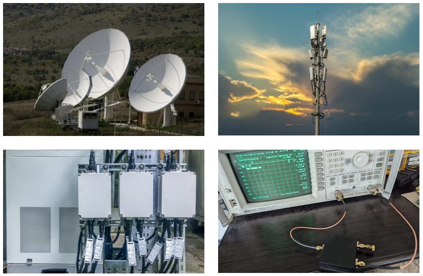
Applications: From Industrial to Communication
RF Splitter Combiners are versatile components found in various sectors.
- Distributed Antenna Systems (DAS):
In large commercial buildings or tunnels, a single base station feed is split into dozens of antennas to ensure uniform coverage. This requires high-reliability splitters that can withstand continuous operation. - Test & Measurement:
Engineers often need to monitor a signal without interrupting the transmission. A splitter allows 50% of the signal to go to the receiver and 50% to a Spectrum Analyzer. - Industrial Connectivity:
Similar to the rugged requirements for industrial Ethernet or aviation connectors (as seen in Renhotec’s product lines), RF components in industrial settings must endure vibration and temperature extremes. High-quality connectors (N-Type, DIN 7/16) are essential interfaces on these splitters to maintain the IP rating and connection integrity.
Choosing the Right RF Splitter
Selecting the correct RF splitter is more than just matching port counts. It requires a holistic view of your system’s environmental and electrical needs.
- Match the Connector Class: Just as you would select a waterproof RJ45 for harsh networking environments, choose RF splitters with rugged connectors like N-Type or 4.3-10 for outdoor or industrial use to prevent moisture ingress and intermodulation distortion (PIM).
- Check Power Handling: If you are using the device as a combiner, ensure it can handle the total summed power and heat dissipation.
- Verify Frequency Coverage: Do not use a narrowband 2.4GHz splitter for a sub-6GHz 5G application.
FAQs
Q: Can I use a splitter as a combiner?
A: Yes, most passive Wilkinson splitters are reciprocal. However, you must ensure the input signals are coherent (same frequency and phase) and that the power levels do not exceed the dissipation rating of the internal isolation resistors.
Q: What is the difference between active and passive RF splitters?
A: A passive splitter distributes signals with some loss (insertion loss) and requires no power. An active splitter contains amplifiers to compensate for the loss (providing unity gain or boost) but adds noise and requires a power source.
Q: Why is 50 Ohm impedance important?
A: 50 Ohm is the standard compromise between power handling and signal attenuation. Using a splitter with the wrong impedance causes reflections (high VSWR), which reduces efficiency and can damage sensitive sources.
Related Products
Contact Us
Do you need high-performance signal distribution solutions for your next project? Whether you require custom cable assemblies, waterproof industrial interconnects, or precision RF components, our engineering team [email protected] is ready to assist. Get a quote or technical consultation today!

Connectors & cable assemblies manufacturer.
Sharing insights on connectors and real-world applications.
Contact for datasheets, samples, or inquiries.
