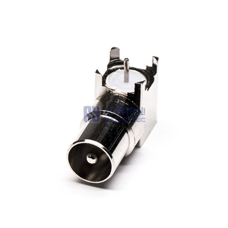


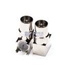

PAL Connector Right Angle Male Plug Solder PCB Mount Through Hole – RHT-627-0058
- PAL right angle male plug connector for PCB mounting
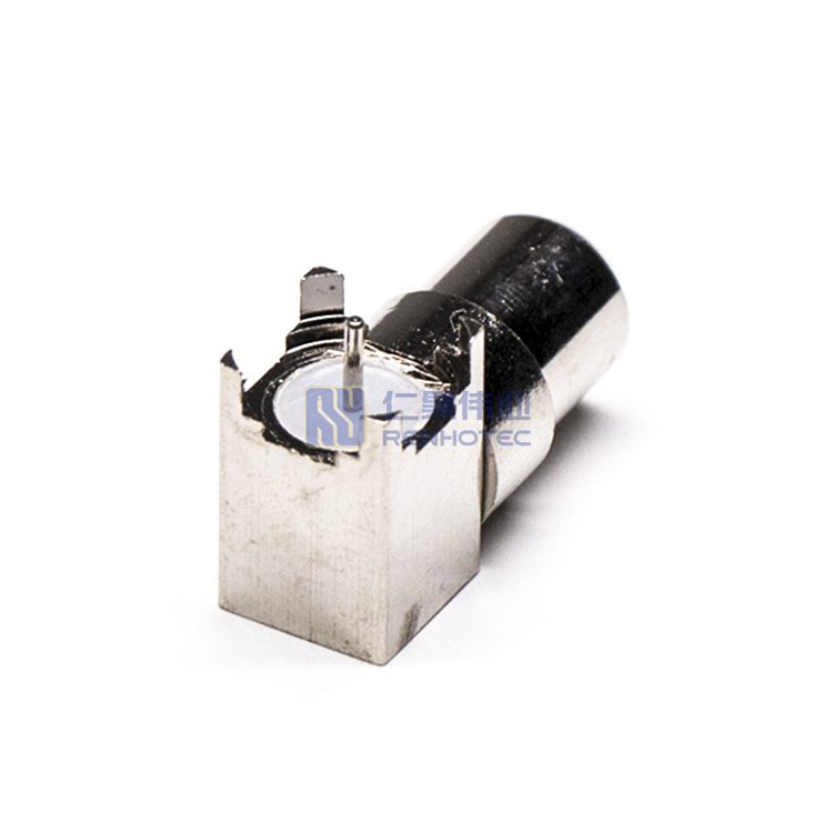
- Through-hole design ensures a secure and stable connection
- Solder type for reliable and durable electrical performance
- Compact size ideal for space-constrained applications
- Used in a variety of RF and communication systems
Product Specification
| RF Series | PAL Type |
||
|---|---|---|---|
| Connector Type | Plug |
||
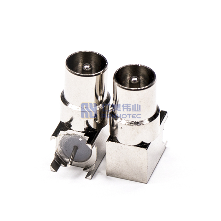
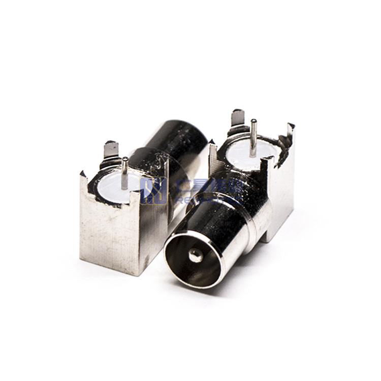
| Orientation | Right Angle |
||
| Contact Type | Male Pin |
||
| Contact Termination Style | Solder |
||
| Shield Termination | Solder |
||
| Mounting Type | Panel Mount |
||
| Mounting Feature | Through Hole |
||
| Number of Ports | 1 |
||
| Impedance | 75 ohm |
||
| Shell Material | Zinc Alloy |
||
| Shell Finish | Nickel Plated |
||
| Insulator Material | PTFE |
||
| Contact Material | Copper Alloy |
||
| Contact Finish | Nickel Plated |
||
| Temperature Range | -40°C to +85°C |
||
| Frequency Range | DC-3 GHz for 75 ohm |
||
| Insultation Resistance | 5000MΩ Min |
||
| RF Series | PAL Type |
Connector Type | Plug |
| Orientation | Right Angle |
Contact Type | Male Pin |
| Contact Termination Style | Solder |
Shield Termination | Solder |
| Mounting Type | Panel Mount |
Mounting Feature | Through Hole |
| Number of Ports | 1 |
Impedance | 75 ohm |
| Shell Material | Zinc Alloy |
Shell Finish | Nickel Plated |
| Insulator Material | PTFE |
Contact Material | Copper Alloy |
| Contact Finish | Nickel Plated |
Temperature Range | -40°C to +85°C |
| Frequency Range | DC-3 GHz for 75 ohm |
Insultation Resistance | 5000MΩ Min |
| RF Series | PAL Type |
|---|---|
| Connector Type | Plug |
| Orientation | Right Angle |
| Contact Type | Male Pin |
| Contact Termination Style | Solder |
| Shield Termination | Solder |
| Mounting Type | Panel Mount |
| Mounting Feature | Through Hole |
| Number of Ports | 1 |
| Impedance | 75 ohm |
| Shell Material | Zinc Alloy |
| Shell Finish | Nickel Plated |
| Insulator Material | PTFE |
| Contact Material | Copper Alloy |
| Contact Finish | Nickel Plated |
| Temperature Range | -40°C to +85°C |
| Frequency Range | DC-3 GHz for 75 ohm |
| Insultation Resistance | 5000MΩ Min |
The PAL connector is also called the IEC connector. The IEC connector is generally attached to the antenna cable. In most cases, it has a male connector on one side and a female connector on the other side. This makes it easy to extend the cable without having to use barrel connectors as we do in the US. This means you can extend the antenna signal more easily and with less loss.

The PAL connector is commonly used in Europe and Australia to connect coaxial cables with each other and with terrestrial VHF/UHF roof antennas, antenna signal amplifiers, CATV distribution equipment, and TV sets, and FM and DAB radio receivers.
Application Scenarios
