In the realm of millimeter-wave (mmWave) applications, the interconnect is no longer just a mechanical junction; it is a critical component of the transmission line. As frequencies push beyond 18GHz into the K, Ka, and Q bands, the margin for error in high frequency RF connectors shrinks significantly. A deviation of a few microns in the center contact or a slight degradation in the dielectric interface can lead to catastrophic signal reflection and phase instability. This deep dive explores the mechanical and electrical nuances that define the reliability of high frequency connectors, specifically focusing on the 3.5mm, 2.92mm, 2.4mm, and SMP interfaces.
The Geometry of Precision: Understanding 3.5mm, 2.92mm, and 2.4mm Interfaces
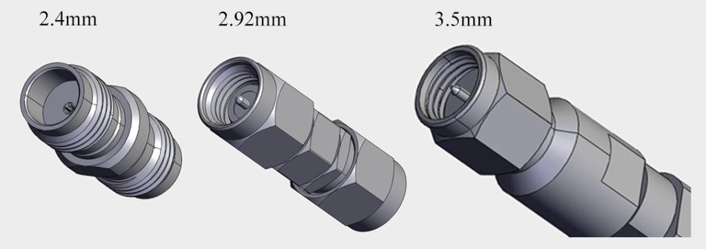
When selecting high frequency coaxial interconnects, the transition from traditional SMA to precision air-dielectric connectors is the first step in maintaining signal integrity. The nomenclature of these connectors—3.5mm, 2.92mm, and 2.4mm—refers to the outer diameter of the air dielectric within the interface. This physical dimension is inversely proportional to the cutoff frequency; as the diameter decreases, the maximum usable frequency increases.
Mechanical Compatibility and the “Air Dielectric” Advantage
Unlike standard RF connectors that use a solid PTFE (Teflon) dielectric, high-performance 3.5mm Connectors, 2.92mm Connectors, and 2.4mm RF connectors utilize an air dielectric. This design minimizes insertion loss and provides a more stable dielectric constant (ϵr≈1.0$) across a broad spectrum.
- 3.5mm Connector: Optimized for frequencies up to 26.5GHz. It features a thicker outer wall than the SMA, offering superior mechanical durability for test and measurement environments.
- 2.92mm Connector (K Connector): Specifically engineered to operate up to 40GHz. It is mechanically compatible with SMA and 3.5mm interfaces, though extreme caution is required to prevent “pin-and-socket” damage during mating.
- 2.4mm Connector: Designed for the 50.0 GHz threshold, the 2.4mm interface is precision-engineered in accordance with IEEE 287-2007 (Standard for Precision Coaxial Connectors). By further reducing the internal geometry and strictly following the air-dielectric specifications of the IEEE 287-2007 laboratory-grade series, this interface eliminates the moding issues common in larger connectors at these frequencies.
The use of air as a dielectric is critical because it avoids the phase changes associated with PTFE “teflon knee” (a phenomenon where the dielectric constant shifts around 19°C). For engineers working on phase-sensitive radar or high-speed digital backplanes, the stability provided by an air-interface 2.92mm Connector is highly recommended for phase-critical applications.
Signal Integrity Challenges in Millimeter-Wave Interconnects
As we operate in the 18GHz to 50GHz range, the electrical performance of high frequency RF connectors is dictated by extremely tight mechanical tolerances. In these microwave bands, a gap of just 0.05mm at the mating interface can introduce inductive or capacitive parasitics that compromise the entire signal chain.
Return Loss and VSWR: Why Millimeters Matter
Voltage Standing Wave Ratio (VSWR) is the primary metric for interface quality. For a 2.92mm Connector operating at 40GHz, maintaining a VSWR below 1.25:1 requires high-precision concentricity within microns of the center conductor.
- Impedance Discontinuity: Any physical step-down or gap at the connector junction creates an impedance mismatch (deviating from 50Ω). At high frequencies, these mismatches result in significant return loss, where signal energy is reflected back to the source, potentially damaging sensitive GaAs or GaN power amplifiers.
- Skin Effect and Surface Roughness: Above 18GHz, current flows primarily on the “skin” of the conductor. The surface finish of the internal contact becomes critical. We utilize advanced gold-plating techniques over a nickel-phosphorus underlayer to ensure a surface roughness (Ra) of less than 0.4μm, minimizing resistive losses.
Common Failure Modes in High Frequency RF Connectors
Reliability in high frequency connectors is often a battle against mechanical wear and environmental physics. Understanding these failure modes is essential for preventive maintenance in aerospace and defense applications.
Mechanical Wear and Mate-Cycle Degradation
The most common failure point is the female “socket” contact. In 3.5mm Connectors and 2.92mm Connectors, the spring fingers of the socket must maintain constant radial pressure on the male pin.
- Contact Fatigue: Repeated mating cycles (typically rated for 500 cycles) can lead to the loss of elastic memory in the beryllium copper (BeCu) base metal. This results in increased contact resistance and erratic phase performance.
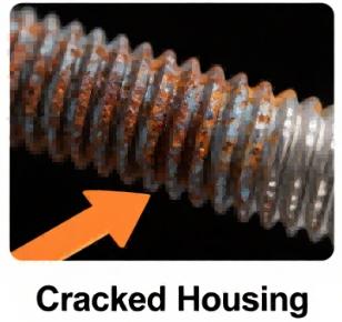
- Debris Contamination: Because these are air-dielectric interfaces, they are “open” to the environment. Microscopic metal shavings from cross-mating a 2.92mm male with a low-quality SMA female can lodge in the air gap, creating a localized dielectric shift or a short circuit.
Environmental Stress: Thermal Expansion and Oxidation
In satellite communications (SatCom), connectors undergo extreme thermal cycling.
- CTE Mismatch: The Coefficient of Thermal Expansion (CTE) difference between the stainless-steel housing and the gold-plated center contact can cause “connector breathing.” As the temperature fluctuates, the center contact may shift axially (piston effect), changing the electrical reference plane.
- Oxidation: While gold does not oxidize, the base materials or thin plating can allow moisture ingress. For SMP Connectors used in outdoor 5G MIMO arrays, IP67 or IP68 sealing is mandatory to prevent salt-spray corrosion from degrading the high-frequency path.
SMP Connectors: Balancing High Density with High Frequency
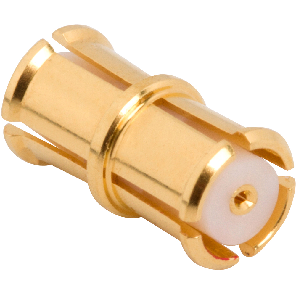
While threaded interfaces like the 2.92mm Connector offer maximum stability, modern phased-array radars and 5G massive MIMO systems require high-density packaging. This is where the SMP Connector (Sub-Miniature Push-on) becomes the industry standard.
Blind-mate Capabilities and Misalignment Tolerances
The SMP Connector is a plug-in interface that allows for “blind-mate” connections, which is essential for backplane-to-card or board-to-board (B2B) architectures.
- Detent Variations: SMPs are available in different engagement forces: Full Detent (maximum retention for high-vibration environments), Limited Detent, and Smooth Bore (lowest engagement force, ideal for multi-port modular testing).
- Radial and Axial Misalignment: One of the most significant engineering advantages of the SMP series is its ability to withstand radial misalignment of up to ±0.5mm (subject to specific series and bullet geometry) when used with a “bullet” adapter (shroud-to-shroud). This flexibility ensures that cumulative mechanical tolerances in a large PCB assembly do not result in connector failure or signal degradation at frequencies up to 40GHz.
Selecting the Right Interconnect: A Purchasing and Engineering Checklist
Sourcing high frequency RF connectors requires a balance between electrical performance, mechanical longevity, and unit cost. For procurement managers and lead engineers, we recommend the following evaluation matrix:
The “Cost of Failure” vs. Unit Price
In satellite or subsea deployments, the cost of replacing a failed 2.4mm RF connector can be 10,000x the price of the component itself. We advise engineers to verify the Internal Laboratory Test Reports of their suppliers. Specifically, look for vibration testing (MIL-STD-202) and thermal shock data to ensure the interconnect can survive the operational environment without phase-jumping.
| Technical Metric | High-Performance Spec | Standard Grade | Engineering Impact |
|---|---|---|---|
| Body Material | Passivated Stainless Steel | Gold-plated Brass | Superior torque resistance and CTE stability. |
| Center Contact | Beryllium Copper (BeCu) | Phosphor Bronze | Better elastic memory for 500+ mate-cycles. |
| Plating Thickness | 50 μin Gold over Nickel | 10 μin Gold | Prevents oxidation; reduces skin-effect losses. |
| Interface Standard | MIL-STD-348 / IEEE 287 | Manufacturer Proprietary | Ensures intermateability across suppliers. |
High Frequency Connector FAQ
Q1: Can I mate a 2.92mm male connector with an SMA female connector?
Yes, they are mechanically intermateable per MIL-STD-348. However, extreme caution is required. A low-quality or worn SMA female can have a misaligned socket that may permanently damage the precision 2.92mm male pin. For laboratory environments, we strongly recommend using a “connector saver” adapter.
Q2: Why is stainless steel preferred over brass for 2.4mm and 2.92mm connectors?
Passivated stainless steel provides significantly higher mechanical hardness and a lower Coefficient of Thermal Expansion (CTE). This ensures the connector maintains its torque setting and electrical reference plane during thermal cycling, which is critical for measurements above 18GHz.
Q3: What is the difference between SMP “Full Detent” and “Smooth Bore”?
It refers to the retention force. Full Detent requires high force to disengage and is used in high-vibration aerospace environments. Smooth Bore has minimal retention, allowing for easy push-on/pull-off, ideal for modular test setups or high-density board-to-board applications.
Contact Our Engineering Team for Custom Microwave Solutions
Navigating the complexities of high frequency coaxial interconnects requires more than just a datasheet. Whether you are designing a 40GHz satellite payload or a 5G massive MIMO array, our engineering team provides:
- Custom Interface Designs: Tailored SMP and 2.92mm solutions for unique PCB layouts.
- Full SI Simulation: HFSS modeling to predict VSWR and Return Loss before prototyping.
- Certified Lab Testing: MIL-STD-202 vibration and thermal shock validation.
Need a technical consultation or a bulk quote for high frequency connectors?
[Contact our RF Application Engineers Today: [email protected]]

Connectors & cable assemblies manufacturer.
Sharing insights on connectors and real-world applications.
Contact for datasheets, samples, or inquiries.