1. What is an RF Splitter & Combiner?
In the realm of Radio Frequency (RF) engineering, an RF splitter (also known as a power divider) is a passive device used to distribute a single input signal into two or more output signals. Conversely, an RF combiner performs the reverse function, merging multiple input signals into a single output path. These components are foundational in modern telecommunications, allowing for complex signal distribution in cellular networks, satellite systems, and laboratory testing environments.
A passive rf splitter operates based on electromagnetic coupling and impedance matching, ensuring that the signal integrity remains intact without requiring external power. Whether you are using an antenna splitter combiner to feed multiple receivers from a single antenna or building a complex phased-array radar, understanding the physics of power division is the first step toward system optimization.
In specialized cases, such as the Active GPS Power Divider, the device incorporates internal amplification to ensure that weak satellite signals are not further degraded by the splitting process. Unlike a standard passive rf splitter, these active versions require a power source—often drawn directly from the connected GPS receiver’s DC bias.
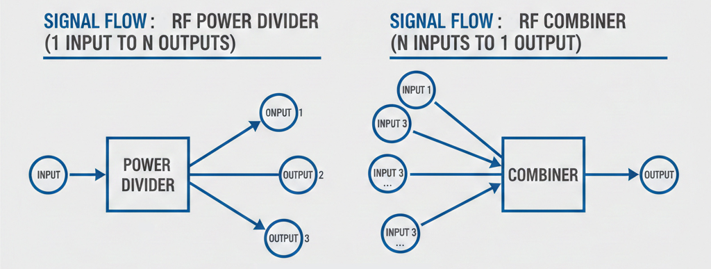
2. RF Power Divider vs. Combiner: Understanding the Reciprocity
A common question among procurement officers and junior engineers is whether these devices are interchangeable. Most RF power dividers are reciprocal, meaning they can function as combiners. However, the application dictates the necessity for specific design considerations.
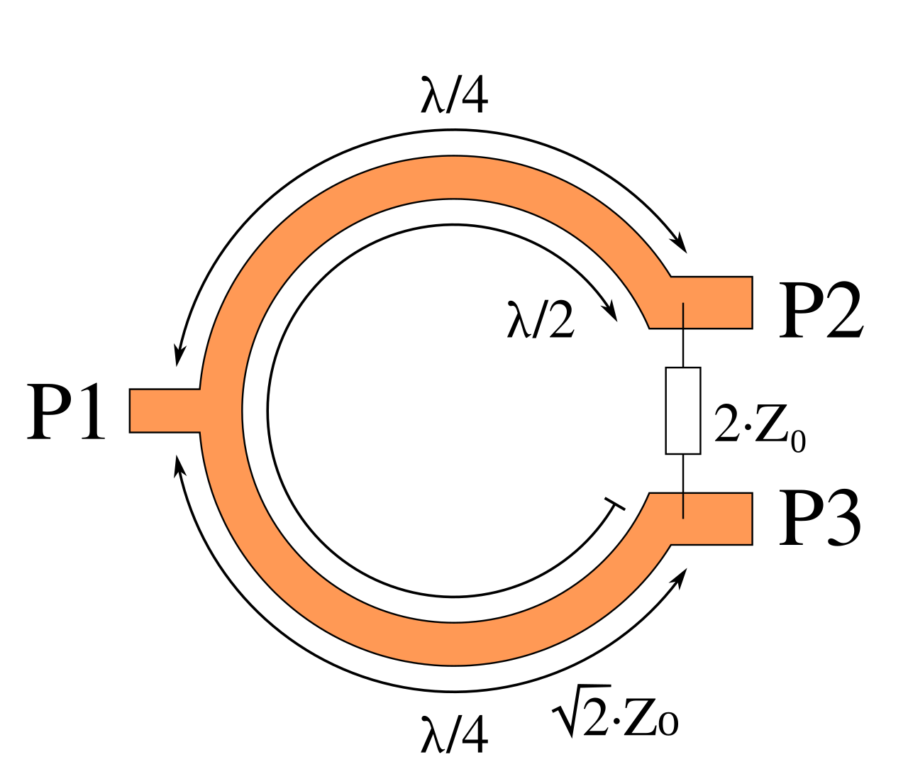
When used as a power splitter combiner, the device must manage the vector sum of the input signals. If the inputs are not in phase, the “lost” power is dissipated as heat within the internal isolation resistors (Wilkinson design). This is why a device rated for 10W as a splitter might have a much lower power rating when used as a combiner for non-coherent signals. According to Microwave Journal (2023), power handling in combiner mode is often limited by the thermal dissipation capacity of internal resistors rather than the main transmission lines.
It is crucial to note that Active Power Dividers are generally non-reciprocal. Because they contain an internal Low Noise Amplifier (LNA) to provide gain, they are designed strictly for signal distribution (Input to Output). Attempting to use an active divider as a combiner can damage the sensitive internal circuitry.
3. Key Technical Parameters for Selection
Selecting the right component requires a deep dive into electrical specifications. Overlooking a single parameter can lead to signal degradation or hardware failure.
Frequency Range
The operational bandwidth is the most critical factor. RF components are designed to maintain a specific Characteristic Impedance (usually 50 Ohms or 75 Ohms) over a defined range. Using a device outside its rated frequency leads to high VSWR (Voltage Standing Wave Ratio). For GPS-specific applications, active dividers are optimized for GNSS bands (L1, L2, L5), ensuring peak performance for positioning and timing data.
Insertion Loss vs Gain
Insertion loss is the total power lost when a signal passes through the device, excluding the theoretical loss caused by the division.
| Configuration | Theoretical Splitting Loss (dB) | Typical Excess Loss (dB) | Typical Total Measured Loss (dB) |
| 2-Way Splitter | 3.01 dB | 0.2 – 0.5 dB | 3.2 – 3.8 dB |
| 3-Way Splitter | 4.77 dB | 0.4 – 0.8 dB | 5.2 – 5.6 dB |
| 4-Way Splitter | 6.02 dB | 0.5 – 1.0 dB | 6.5 – 7.5 dB |
| 8-Way Splitter | 9.03 dB | 0.8 – 1.5 dB | 9.8 – 10.5 dB |
| 16-Way Splitter | 12.04 dB | 1.2 – 2.5 dB | 13.5 – 15.5 dB |
In an active GPS power divider, the “Insertion Loss” is often replaced by a “Gain” specification. This gain compensates for both the split loss and long cable runs, maintaining a high Signal-to-Noise Ratio (SNR).
DC Bias Management (Specific to Active Models)
A unique parameter for GPS splitters is DC Pass/Block functionality. Active dividers must manage the DC voltage required to power the external active antenna. Typically, one port is designated as “DC Pass” to provide power to the antenna, while the others are “DC Blocked” to prevent voltage conflicts between multiple connected receivers.
Isolation
Isolation measures the “leakage” between output ports. High isolation (typically >20dB) is required to ensure that a fault or reflection in one branch does not affect the others. This is vital in antenna splitter combiner setups where multiple transmitters share a system.
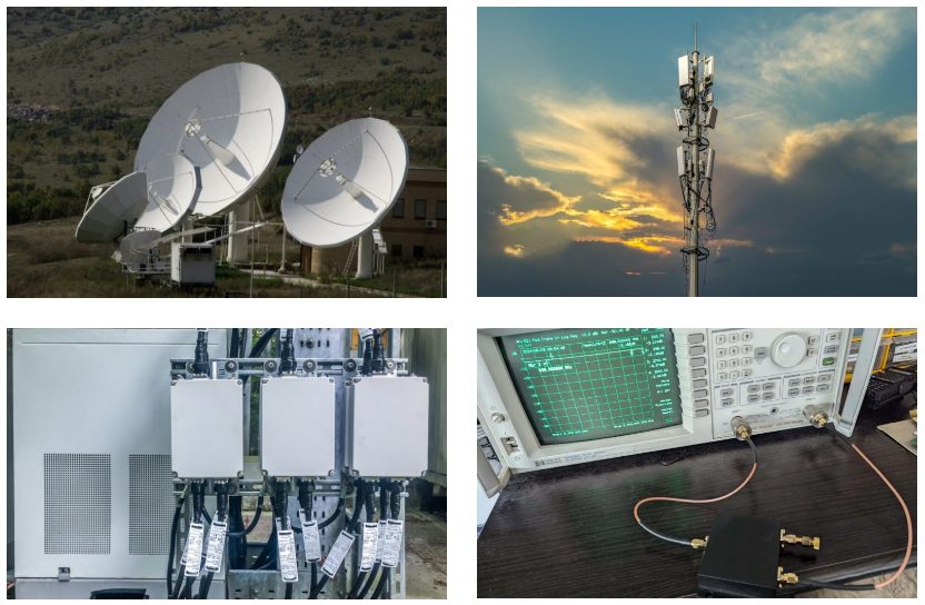
4. Typical Applications of RF Power Splitters
The versatility of the rf power divider makes it indispensable across various sectors:
- Wireless Infrastructure (DAS, Distributed Antenna System): Distributing cellular signals across multiple floors in a building using an 8 way power divider.
- Satellite Communications: Combining signals from multiple low-noise amplifiers (LNAs) into a single down-converter.
- Test and Measurement: Using a 3 way rf combiner to inject multiple interference signals into a device under test (DUT) to evaluate its robustness.
- Broadcasting: Feeding multiple transmitter towers from a single signal source to ensure synchronized coverage.
- GPS/GNSS Distribution: Using an active GPS power divider in data centers, laboratories, or telecommunication hubs where a single outdoor roof antenna must serve dozens of indoor timing receivers.
5. How to Choose the Right RF Splitter/Combiner
When moving toward a purchase decision, follow this structured checklist:
- Define Port Requirements: Determine if you need a 3 way rf combiner, a 4 way rf combiner, or a high-density 16 way power divider.
- Verify Power Handling: Ensure the device can handle the peak and average power of your transmitters. For high-power applications, look for “High Power” series with N-type or 7/16 DIN connectors.
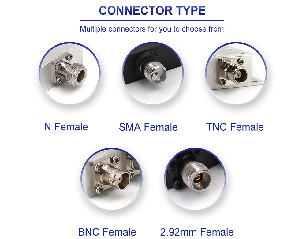
- Connector Type: Match the connectors to your existing system (SMA for lab/small scale, N-type for outdoor/industrial).
- Environmental Rating: For outdoor use, specify IP65 or IP67 ratings to protect against moisture.
- Active vs. Passive: Choose an Active model if you are distributing GNSS signals and need to overcome cable loss. Choose Passive for general-purpose, high-power, or bidirectional RF tasks.
FAQ
Q1: Can I use an 8-way power divider if I only have 6 outputs?
A: Yes, but you must terminate the 2 unused ports with high-quality 50-Ohm dummy loads. Leaving them open will cause reflections that degrade the performance of the remaining 6 ports.
Q2: What is the difference between a Power Divider and a Directional Coupler?
A: A power divider splits power equally (usually), while a directional coupler samples a small fraction of the power (e.g., -10dB or -20dB) from the main line for monitoring purposes.
Q3: Does a 16-way power divider cause more signal delay than a 2-way?
A: Generally, yes. The complex internal routing of a 16 way power divider results in a slightly longer electrical path and higher group delay compared to a simple 2-way device.
Q4: What happens if I connect multiple receivers to one active GPS splitter?
A: A professional-grade active splitter will manage the DC bias correctly, ensuring only one receiver (or an internal regulator) powers the antenna, while protecting the other receivers from reverse voltage.
Contact Us
Need a custom rf power divider or an active GPS power divider for your project? Our engineering team [email protected] specializes in high-performance passive rf splitter solutions for 5G, Aerospace, and Defense.

Connectors & cable assemblies manufacturer.
Sharing insights on connectors and real-world applications.
Contact for datasheets, samples, or inquiries.
