Introduction
In the rapidly evolving landscape of wireless communications—spanning from 5G networks to advanced radar systems—the physical interface connecting your hardware is often the critical bottleneck. RF (Radio Frequency) connectors are the specialized interfaces designed to join coaxial cables, ensuring continuous signal integrity by matching impedance and reducing electromagnetic interference (EMI).
However, as we push into the microwave and millimeter-wave spectrums, a generic connector is no longer sufficient. This brings us to a pivotal decision for engineers and buyers: High Frequency Connectors vs. Standard RF Connectors. Understanding the nuances between a rugged BNC connector and a precision 1.0mm interface can mean the difference between crystal-clear data transmission and catastrophic signal loss.
This guide analyzes the structural and performance differences to help you select the right component for your specific application.
What Are Standard RF Connectors and High Frequency Connectors?
Before diving into specifications, it is essential to categorize these components based on their primary utility.
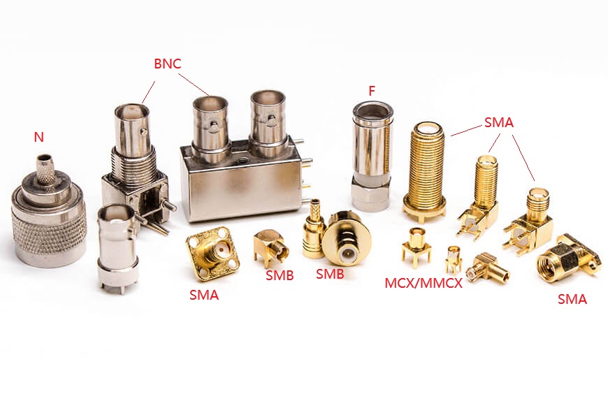
Standard RF Connectors are typically defined by their utility in broadcasting, video, and general telecommunications. These include interfaces like UHF, N-type, and BNC connectors. They are engineered for durability and cost-effectiveness in frequencies generally below the microwave range (1-6 GHz). They prioritize robust mating cycles and ease of use over extreme precision.
High Frequency Connectors, often referred to as precision or microwave connectors, are engineered for the microwave (GHz) and millimeter-wave frequencies. Examples include 2.92mm, 1.85mm, and 1.0mm connectors. These are designed with tighter mechanical tolerances to minimize reflections and support frequencies ranging from 18GHz up to 110GHz. They are critical for test and measurement (T&M), satellite communications, and high-speed data transmission.
Note: While many standard connectors handle RF signals, not all qualify as “High Frequency” in the modern context of mmWave technology.
Core Differences: From Structure to Performance
The distinction between high frequency and standard connectors spans five key dimensions: interface, size, frequency, standards, and function.
Interface Types
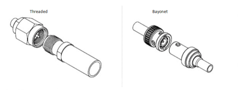
- Standard (Bayonet/Threaded): Standard connectors often use Bayonet connections (like BNC), featuring a twist-and-lock mechanism for fast mating in video applications. While convenient, this mechanism is less stable at high frequencies compared to threaded designs.
- High Frequency (Precision Threaded/Blind): High frequency connectors almost exclusively use Threaded connections (like SMA or 2.92mm) to ensure a gap-free junction. For dense PCB assemblies, Blind (Floating) connections are used, allowing misalignment in X, Y, and Z directions while maintaining signal integrity.
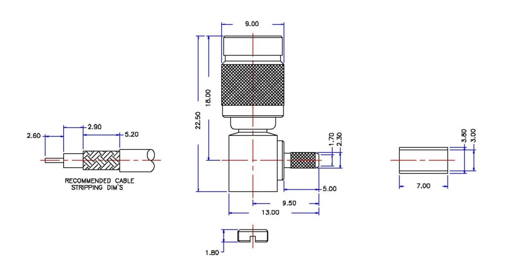
Size and Tolerance
Physics dictates that as frequency increases, wavelength decreases. Consequently, High Frequency Connectors must be physically smaller to prevent higher-order modes from propagating.
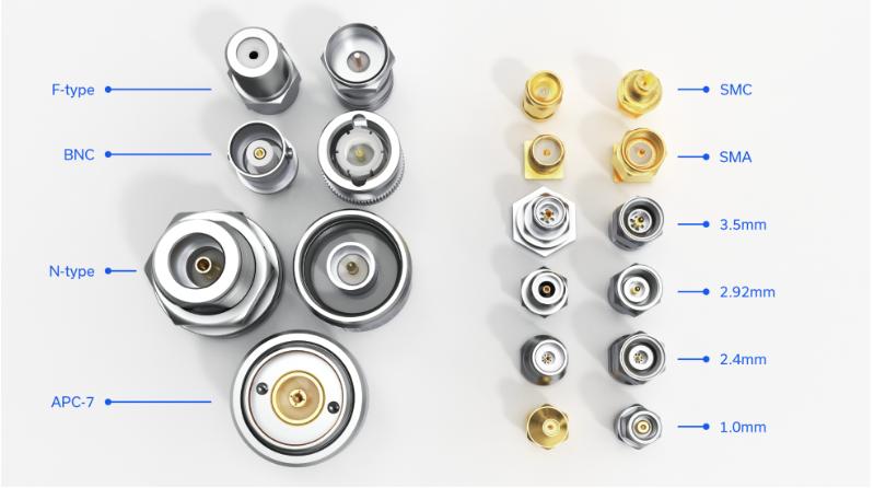
- Standard: Large types like 7/16 or N-Type.
- Ultra-Small: SMA, SMB, MCX.
- Miniature/Precision: 2.92mm, 1.85mm, 1.0mm.
Frequency Range Classification
The most distinct differentiator is the operational spectrum.
| Category | Frequency Range | Typical Applications | Connector Examples |
|---|---|---|---|
| Audio/Video | < 500 MHz | CCTV, Broadcast Radio | RCA, UHF |
| Radio (Standard) | 500 MHz – 6 GHz | WiFi, LTE, GPS | BNC, TNC, N-Type |
| Microwave (High Freq) | 18 GHz – 110 GHz | 5G, Radar, Satellite | SMA, 2.92mm, 1.0mm |
Deep Dive: High Frequency Solutions (Breaking the GHz Barrier)
Selecting the correct high-frequency connector is about matching the connector’s cutoff frequency to your system’s needs. Here is a breakdown of the specific models mentioned in industry references.
SMA Connector (0-22GHz)
The SMA (SubMiniature version A) is the workhorse of the RF industry. It features a compact design with a PTFE-filled mating space.
- Pros: widely available, cost-effective.
- Cons: Early generations had limitations in precision alignment; modern iterations address this but still generally cap at 22 GHz.
3.5mm Connector (Up to 34GHz)
Developed in the 1960s, the 3.5mm connector utilizes an air dielectric (rather than PTFE) to achieve higher frequencies.
- Key Feature: Designed to mate with SMA connectors mechanically, but with significantly better electrical performance and durability.
2.92mm Connector (Up to 40GHz)
The 2.92mm connector is the industry standard for high-performance testing.
- Performance: It offers excellent concentricity and stress relief.
- Compatibility: It mates with SMA and 3.5mm connectors, making it versatile for upgrading existing systems without replacing every cable.
2.4mm, 1.85mm, and 1.0mm (The Millimeter-Wave Giants)
For applications requiring extreme performance (50 GHz to 110 GHz), the geometry must shrink further.
- 2.4mm: Operates up to 50GHz with a robust wall design. Note: Does not mate with SMA.
- 1.85mm: Often called the “V connector,” it pushes operations to 65GHz.
- 1.0mm: The frontier of coaxial connectivity, supporting up to 110GHz for specialized metrology and research.
Critical Performance Parameters
When upgrading from standard to high-frequency connectors, three parameters define the quality of the signal.
Impedance Matching
The “Characteristic Impedance” is determined by the dimensions of conductors and the dielectric constant.
- Standard: 75Ω is common for video/broadcast.
- High Frequency: 50Ω is the universal standard for RF power transfer. Matching impedance across the entire cable assembly minimizes reflections.
VSWR and Reflection
VSWR (Voltage Standing Wave Ratio) measures how much signal is reflected back towards the source due to impedance mismatches.
- Goal: A low VSWR (close to 1:1) indicates efficient power transfer. In high-frequency systems, even a loose thread or poor connector tolerance can spike VSWR, causing data errors.
Attenuation (Signal Loss)
Attenuation describes the loss of signal strength as it travels, measured in decibels (dB). Loss increases naturally with frequency (Skin Effect). High-frequency connectors use specialized materials (like Gold-plated Beryllium Copper) and air dielectrics to minimize this loss.
Selection Guide: How to Match the Connector to the Application
Not every application requires a $100 precision connector. Use this matrix to guide your procurement strategy.
- For Military & Aerospace (MIL-STD): Look for connectors compliant with MIL-C-39012 (GJB681). These require robust threaded interfaces (TNC, SMA) designed for vibration resistance and harsh environments.
- For Lab & Metrology: Prioritize Precision Grades (Grade 0 or 1). Connectors like the 2.92mm or 1.85mm are essential here. They offer high repeatability for accurate measurements.
- For Consumer/Portable Devices: Space is the limiting factor. Use Ultra-small or Snap-on connectors like MCX or SMB. While they may not reach 50 GHz, they offer the best balance of size and performance for WiFi/Bluetooth frequencies.
Feature Products
High Frequency Connectors
RF Connectors
Contact Us
Upgrading your RF signal chain requires more than just buying cables—it requires precision engineering. Whether you need robust Standard RF Connectors for industrial deployment or high-performance 2.92mm Connectors for 5G testing, selecting the right interface is critical.
Need help calculating the impedance or selecting the right interface for your project? Contact our RF Engineering Team to ensure your data travels without loss.
📞 Phone: +86 180 8661 0187
📧 Email: [email protected]

As a Product Manager at Renhotec Group (est. 2008), I specialize in providing deep technical insights into connectors, cables, and custom electronic components. Renhotec is a global leader in interconnect solutions, dedicated to manufacturing high-standard products for diverse industries as your trusted technical partner.