Introduction
Coaxial connectors are indispensable components in modern electronic communication, serving as the critical interface between cables and devices to ensure efficient signal transmission. Among the vast array of available types, the Type N connector and the Type F connector stand out as two of the most ubiquitous, yet fundamentally different, solutions. While both facilitate the connection of coaxial cables, they are designed for entirely separate applications, operating environments, and signal characteristics.
Choosing between Type N vs Type F connectors depends primarily on your system’s impedance and frequency range requirements. While the N-type connector is a 50-ohm rugged interface supporting up to 11GHz, the F-type coaxial cable connector is a 75-ohm standard commonly used in cable TV and satellite applications. In this guide, we compare their mechanical structures, signal loss performance, and specs to help you make the right selection.
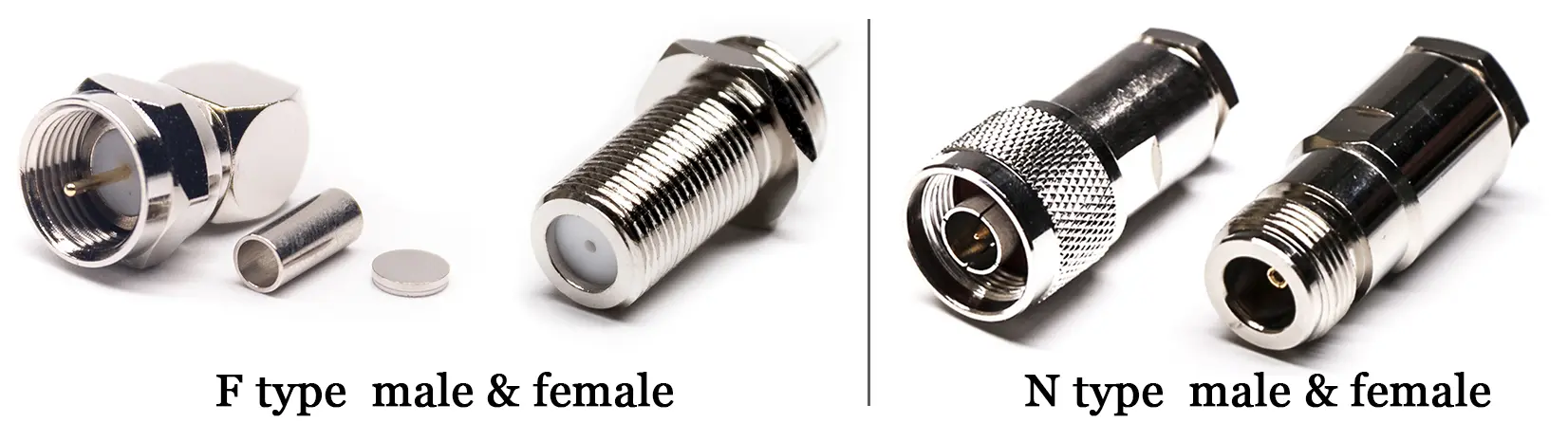
What is an N Type Connector?
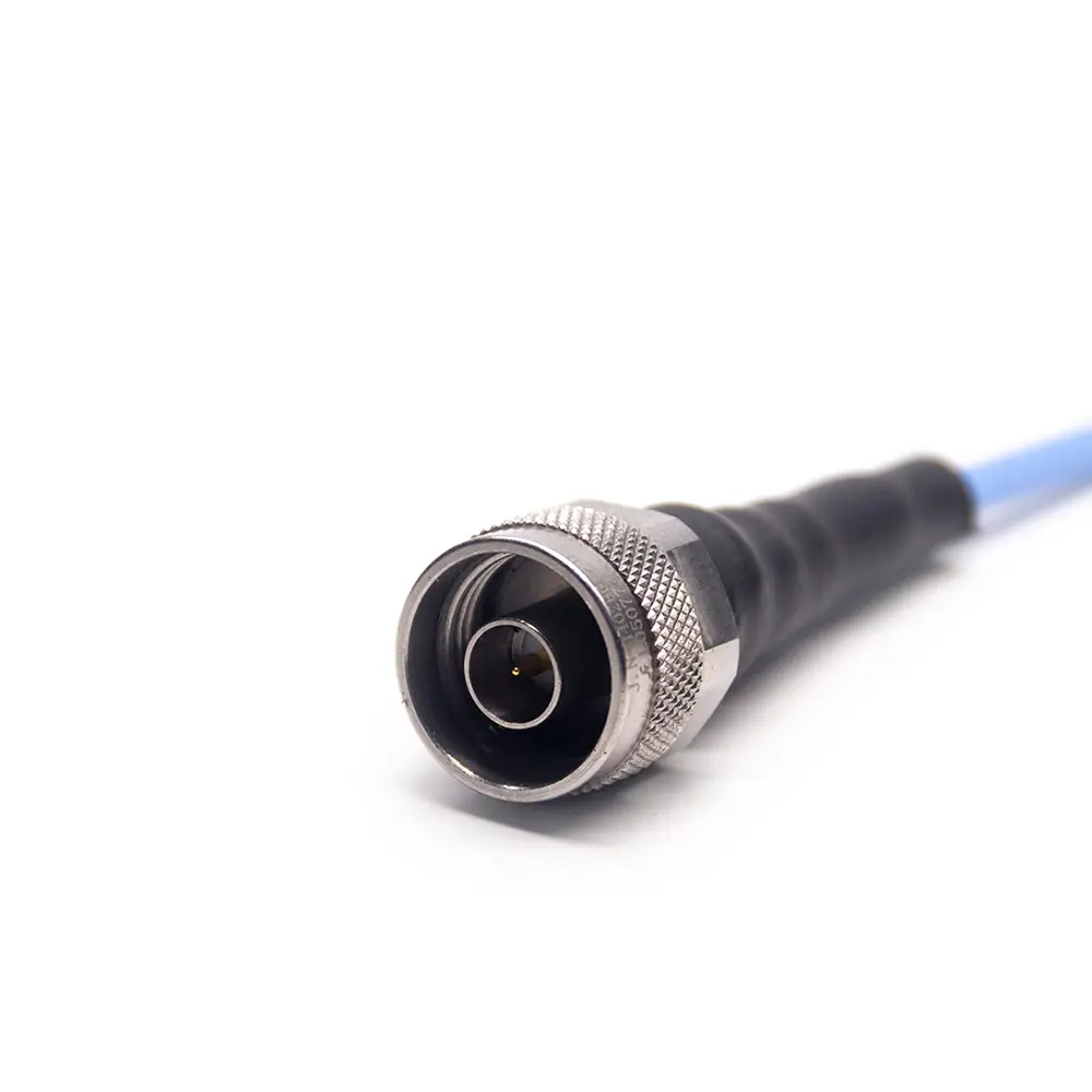
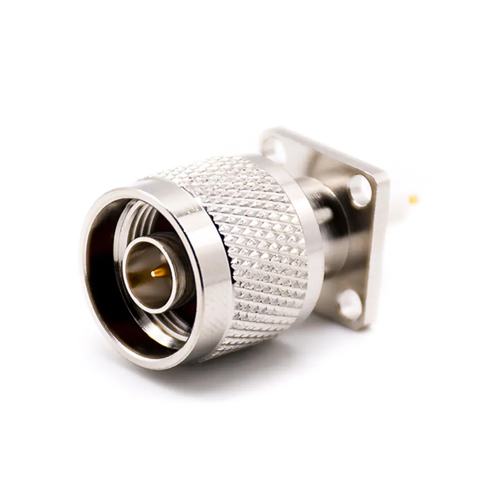
The Type N RF connector (type n coax connector) is a medium-sized, threaded, weatherproof coaxial connector invented by Paul Neill of Bell Labs in the 1940s. It was the first connector capable of handling microwave frequencies. The N-type is primarily associated with 50Ω impedance systems, making it the dominant choice in professional radio frequency (RF) and microwave applications.
Key Characteristics
- Impedance: Typically 50Ω. A less common 75Ω version exists, but is usually incompatible with 50 ohm components.
- Frequency Range: Standard N-type connectors can operate up to 11 GHz, while precision versions are rated for up to 18 GHz.
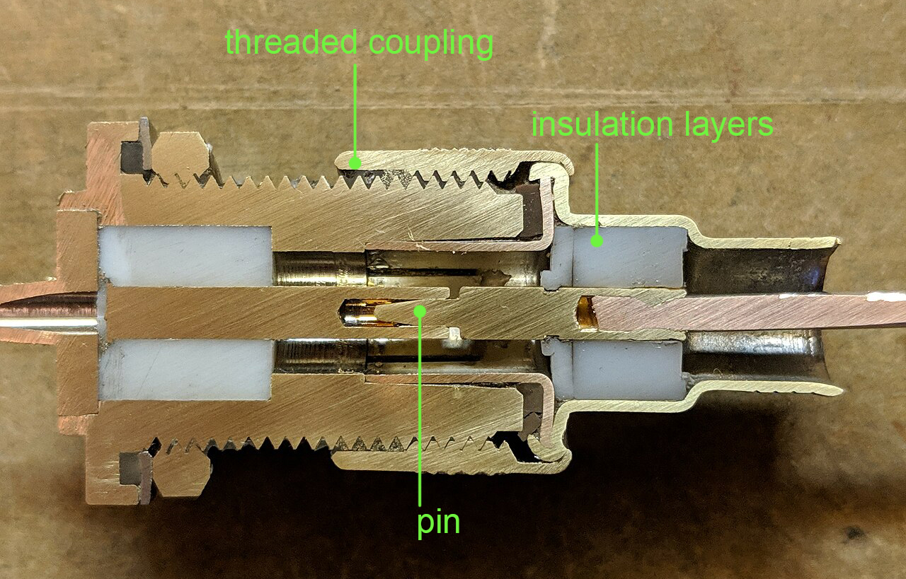
- Mechanical Design: Features a robust, threaded coupling mechanism that ensures a secure, low-resistance connection and provides excellent resistance to vibration and physical stress.
- Weatherproofing: N-type connectors are typically designed to be IP-rated (Ingress Protection) and are widely used in harsh outdoor environments.
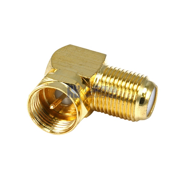
What is an F Type Connector?
The F type coax connector is a relatively inexpensive, simple screw-on or push-on coaxial connector, primarily designed for over-the-air terrestrial television, cable television (CATV), and satellite television systems. It operates almost exclusively in 75Ω impedance systems.
Key Characteristics
- Impedance: Universally 75 ohm, matching the characteristic impedance of standard video and cable distribution systems (e.g., RG-6, RG-59).
- Frequency Range: Typically used up to 1 GHz or 3 GHz, suitable for broadband video and data applications.
- Mechanical Design: A crucial design feature is that the center conductor of the coaxial cable itself forms the central pin of the connector. This simple design significantly reduces manufacturing costs and complexity. The part that screws onto a device is commonly referred to as a F plug connector.
- Coupling: Most common versions utilize a simple screw-on nut, offering a secure connection but generally less weather-resistant than Type N.
Difference Between N Type and F Type Connector
The choice between a Type N and a Type F connector fundamentally depends on the required Impedance and Application. Attempting to use these connectors interchangeably is highly discouraged.
N Type Vs F Type Impedance and Frequency
This is the most critical technical difference. Impedance dictates the resistance the cable and connector present to the AC signal, measured in Ohms (Ω).
| Feature | Type N Connector | Type F Connector |
| Characteristic Impedance | 50 Ohms (Ω) | 75 Ohms (Ω) |
| Primary Application | RF Transmission, High Power | Video & Data Transmission, CATV |
| Typical Max Frequency | Up to 11 GHz (Standard), 18 GHz (Precision) | Up to 3 GHz |
| Signal Integrity | Designed for optimal power transfer (50 Ω is a practical balance for power handling and high-frequency performance). | Designed for optimal voltage transfer in video systems. |
One of the most significant performance gaps lies in the bandwidth. The n type connector frequency range is vastly superior to the F-type (which usually caps at 3 GHz), allowing it to handle high-frequency signals with minimal insertion loss and better VSWR (Voltage Standing Wave Ratio).
Mechanical Design and Durability
| Feature | Type N Connector (50 Ω) | Type F Connector (75 Ω) |
| Coupling Mechanism | Threaded (Secure, Robust) | Threaded or Push-On (Simpler, faster) |
| Center Conductor | Independent, dedicated male pin (Gold or Silver Plated) | The center conductor of the cable itself |
| Weather/Sealing | Excellent (often sealed with gaskets); Designed for outdoor use. | Minimal to none; Primarily for indoor/dry applications. |
| Cost | High (Precision-machined parts) | Low (Mass-produced, minimal parts) |
The reliance of the F type connectors coaxial cable on the cable’s center wire for its pin makes it extremely cost-effective. However, the robust, screw-in design of the N-type such as right angle n type connector, which features a fully encapsulated dielectric and an independent center pin, provides superior reliability and performance under stress.
Common Applications
The application dictates the connector type, as the environment and signal characteristics must align with the connector’s design intent.
- Type N Applications (High-Performance RF):
- Cellular Base Stations (BTS) and Repeaters.
- High-power Antenna connections (Wi-Fi, Public Safety).
- Radio Transmitters and Receivers.
- Test and Measurement Equipment.
- All environments require 50Ω impedance.

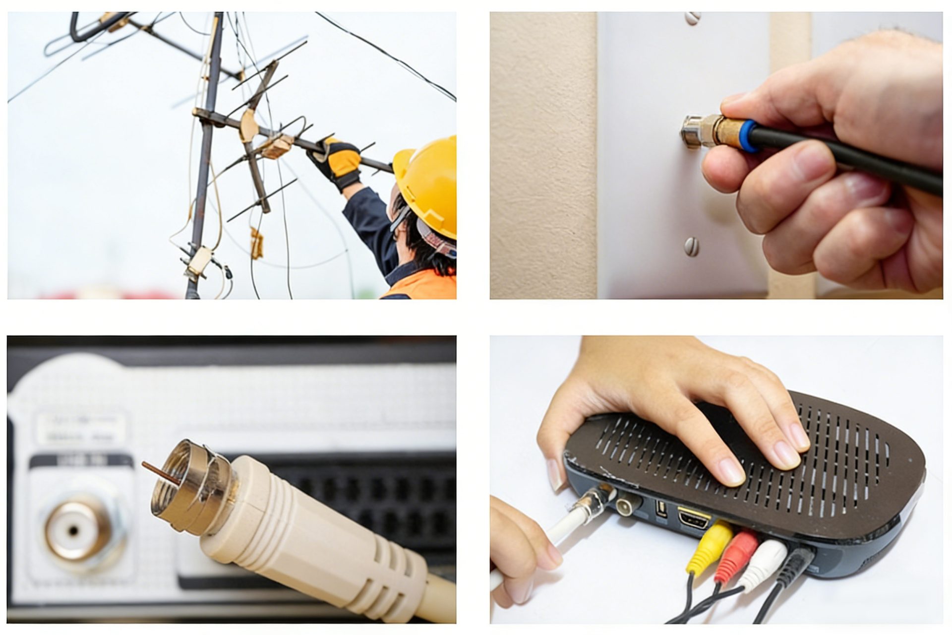
- Type F Applications (Consumer Video/Data):
- Connecting cable modems to wall outlets.
- Satellite TV LNBs and receivers.
- Standard TV and VCR connections, which typically use a F type female connector port.
- All environments require 75Ω impedance.
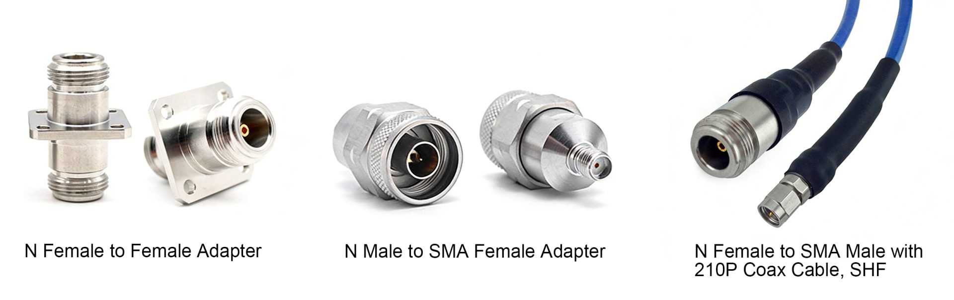
Adapters and Cabling Solutions
While Type N and Type F are incompatible by design, cross-system integration is often necessary. This requires specialized coaxial adapters or cable assemblies that correctly terminate both ends.
- Connecting 50Ω Devices (Type N) to other RF Standards (e.g., SMA):
- When connecting a cellular booster antenna (N-Type) to the booster unit (SMA), an adapter like an N male to SMA female adapter or a custom N to SMA cable assembly is required.
- These adapters often perform a simple mechanical conversion without changing the 50Ω impedance.
- Cable Extensions and Gender Changes:
- For extending N-Type cables, an N female to N female adapter is used.
- The connector gender (male/female) should always be specified when ordering; for example, an N type male often refers to the connector on the cable end.
- Impedance-Matching Conversion (Rare and Complex):
- Converting between a 50Ω system and a 75Ω system should never be done using a simple mechanical adapter. It requires an impedance-matching device (like a balun or minimum loss pad) to prevent reflections.
How to Choose the Right Connector?
Selecting the correct connector hinges on three main questions:
- What is the System Impedance?
- If the system is used for CATV, video distribution, or standard home cable (RG-6/RG-59), choose 75Ω (Type F).
- If the system is for high-power wireless, cellular, radar, or lab testing, choose 50Ω (Type N).
- What is the Operating Environment?
- For indoor, dry applications with minimal handling, the cost-effective Type F is sufficient.
- For outdoor, high-vibration, or industrial applications, the sealed, robust Type N is mandatory.
- What is the Frequency and Power Requirement?
- For frequencies above 3 GHz or high power levels, the superior electrical isolation and construction of the Type N are required. For lower frequencies and consumer power levels, Type F will suffice.
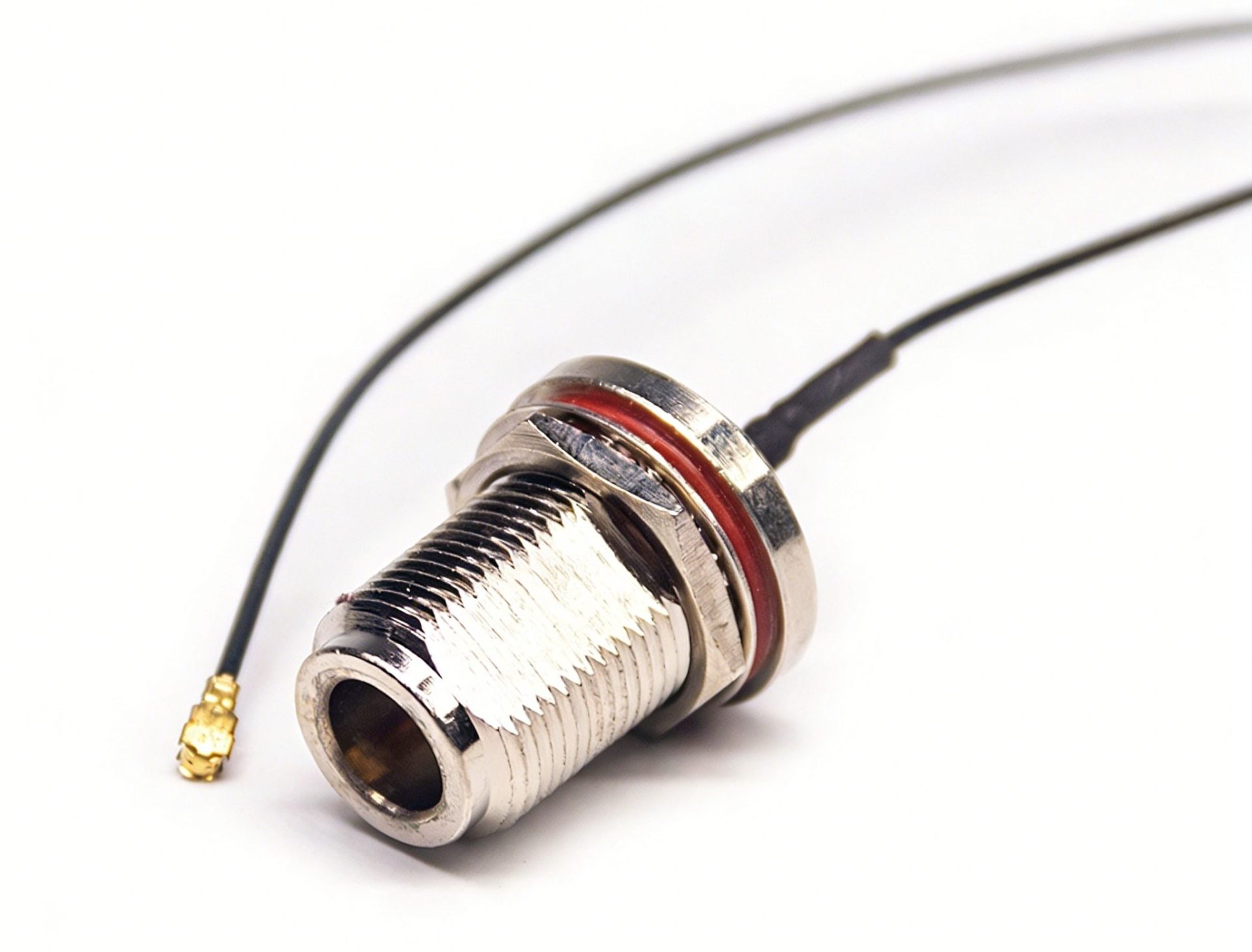
Practical Connectivity Solutions: Bridging Internal Modules and External Antennas
In many real-world RF designs, choosing between Type N and Type F is only half the battle. Engineers often face the challenge of connecting compact internal RF modules—such as Wi-Fi cards or cellular modems—to high-performance external antennas.
Since these internal modules typically utilize ultra-miniature ports, a specialized cable assembly is required to bridge the gap. For instance, in industrial IoT gateways where a rugged outdoor antenna is necessary, using a high-quality ipex to n type pigtail cable is the standard industry practice. This allows the signal to transition seamlessly from the tiny IPEX interface on the PCB to the heavy-duty Type N bulkhead mounted on the device enclosure, ensuring both mechanical stability and low signal loss in demanding environments.
FAQ
Q: Can I plug a Type F connector into a Type N port?
No. While they may appear similar in size, they are mechanically and electrically incompatible. Forcing them can damage the connector and will lead to an severe impedance mismatch (50 Ohm vs 75 Ohm), causing massive signal loss and system degradation.
Q: Is the Type N connector always 50Ω?
Yes, for 99% of modern RF and industrial applications, the Type N connector is a 50Ω connector. The 75Ω version exists but is rare and easily distinguishable by specialized markings or a smaller diameter center pin.
Q: What types of coaxial cable are used with F connectors?
Type F connectors are most commonly paired with 75Ω cables such as RG-6 (the modern standard for CATV) and RG-59 (older standard).
Q: Why are Type N connectors used for antenna connections instead of F connectors?
Type N connectors are preferred because they offer superior weatherproofing, the 50Ω impedance required by most RF transmission equipment, and a stronger mechanical coupling that withstands outdoor elements and wind load.
Q: How do I connect a 50Ω N-Type antenna to a cellular modem with an SMA port?
You must use a specialized n to sma cable assembly or an n male to sma female adapter. This provides the necessary mechanical conversion while maintaining the intended 50Ω impedance across the cable run.
Related Products
Contact Us
Need assistance in selecting the perfect N-Type or F-Type solution for your specific application or need to know the specification? Contact our technical sales team [email protected] for expert guidance and customized product recommendations!

Connectors & cable assemblies manufacturer.
Sharing insights on connectors and real-world applications.
Contact for datasheets, samples, or inquiries.